
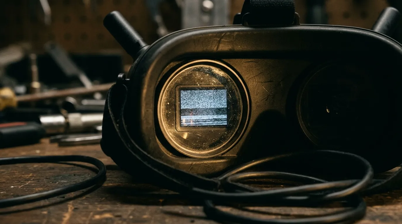
The picture goes to snow without the motors running
Whole-frame grain, evenly spread, present at idle and at full throttle alike. That is the fault this article is about: FPV video noise that arrives as uniform static, gets worse with distance, and gets worse again when an antenna is not fully seated. Grain that pulses with throttle, or that appears the moment the ESCs power up, belongs to the supply path instead — a different branch of the same tree, and not one this article follows. The cluster this article belongs to is interference and video fault troubleshooting.
Here is the sentence worth carrying into the field: snow begins when the signal arriving at the receiver falls to its noise floor, and an FM video link has a threshold below which picture quality collapses far faster than the incoming carrier does. Everything that follows is a way of finding which variable pushed you across that threshold.
What FPV video noise actually is
An analog FPV camera outputs composite video: luminance, chroma and sync multiplexed onto one conductor, referenced to ground. The transmitter puts that composite signal onto an RF carrier by frequency modulation, and the receiver takes it back off. Nothing in that chain is digital, so nothing in it fails in blocks or freezes. It degrades continuously — and the way it degrades is not linear.
FM behaves unusually here. Above a certain carrier-to-noise ratio the demodulated picture is essentially clean; the receiver's limiter strips amplitude noise and the output looks better than the incoming carrier would suggest. Below a different, lower carrier-to-noise ratio — the noise threshold — that advantage reverses and the output becomes worse than a simpler modulation scheme would produce at the same signal level (FM, noise threshold and full quieting). Between those two points the picture does not fade gently. It holds, holds, then goes.
That shape is why snow is such a poor guide to what broke and such a good guide to how much margin is left. The grain on the screen is not your video signal degrading; it is the receiver amplifying its own noise floor once there is no longer enough carrier to suppress it. The screen is showing you the absence of information, which is why no amount of staring at a single frame will tell you whether the missing carrier was lost in the transmitter, in the air, or in the receiver front end.
Two things go before the picture does, and both are useful. Color is carried in a narrower slice of the deviation than luminance, so chroma turns noisy and desaturated while the image is still readable. Sync is next: horizontal sync weakens, the frame starts to tear or roll, and only then does the raster dissolve into video noise proper. If you have been calling the whole progression "static", that ordering is the part worth writing down.
Three places the link can fail before the picture reaches you
Splitting the chain into three is not pedantry. Each third leaves a different fingerprint on the picture, and the fingerprints are separable at the field without instruments.
Transmit side. The VTX output stage delivers less than its setting implies when the antenna port is unterminated or damaged, when the module is hot enough that its output drops — some modules derate, many simply drift — or when the supply sags under load. A transmitter that is quiet because it is protecting itself looks, from the goggles, exactly like a transmitter that is far away.
The path. Free-space loss with distance is the obvious term, but the terms that surprise people are obstruction and polarization. A treeline, a ridge, a building corner all cost margin that no power setting recovers. Cross-polarized antennas — one linear, one circular, or two circular of opposite hand — throw away a large fraction of the link before distance enters the arithmetic at all. Reflections arrive late and add or subtract, which is how a stable picture becomes a pulsing one; multipath does not care how much power you send, only how the geometry adds up.
Receive side. A VRX front end can be deaf, or it can be deafened. A receiver working next to another transmitter on a nearby frequency is being overloaded, not helped: the front end loses sensitivity across the whole band it is asked to cover, so the picture collapses earlier than the distance alone would explain, and it does not recover as you fly back toward your own launch point. Two antennas on a diversity receiver only help if what reaches them differs; two of the same type, both vertical and mounted a fraction of a wavelength apart on the same mast, collect nearly the same signal and behave close to one antenna with extra cable — space them out or orient them differently, and the second one starts earning its connector. Sensitivity figures are worth comparing only with their test conditions attached — a receiver quoted without bandwidth and without a stated criterion is a datasheet ornament, not a spec.
Where it fails | What the picture does | What still looks normal |
|---|---|---|
Transmit output | Grain everywhere, unchanged by antenna swaps, worse when the module is hot | Receiver antenna and cabling check out |
Path (distance, obstruction, polarization) | Grain grows smoothly with distance or with heading; recovers when you turn back | Close-range picture is clean on the same setup |
Receive front end | Grain appears early and stops improving past a certain distance | Transmitter is cool, antenna seated, close range clean |
The link arithmetic behind that second row — what each block contributes and which term dominates at which range — is a subject of its own; here the only thing that matters is that the three rows are distinguishable by when the grain starts, not by how it looks.
Reproduce it without moving anything
A fault you cannot reproduce is a fault you will chase with parts. Before changing a single component, make the failure repeatable, because everything later is a comparison and comparisons need a control.
Pick a launch point and stay on it. Note the coordinates, not "the field behind the shed". Fly the same line three times: out along the same heading, same altitude, same attitude, same throttle profile. What you are measuring is the distance at which the first visible grain appears — not the distance at which the picture becomes unusable. The first grain is the threshold crossing; the unusable picture is everything after it.
Three passes, then compare the three numbers. If they agree within a small margin, you have a baseline and can start changing variables. If they do not agree — if the distance at first grain moves by a third between passes with nothing touched — the variable is not one you introduced. Candidates in rough order of likelihood: a pack that is sagging differently on the third flight, a module that is hotter than it was on the first, another aircraft on the field, or an antenna that shifted on its mount during the previous landing. Chase that instability first. Measuring against a moving baseline produces conclusions that do not survive the next session.
Write the columns down as you go, because memory reconstructs a flattering version of events:
Column | Why it is in the sheet |
|---|---|
Position and heading | Without it, no pass is comparable to another |
Antenna (type, orientation, which port) | The most common single variable, and the easiest to change accidentally |
Band and channel | Two different bands are two different experiments, not one |
Distance at first grain | The measurement; everything else is context |
Ambient (time of day, other aircraft, temperature feel) | Explains the pass that does not fit |
Change one variable per pass: antenna, band, then power
The order is not arbitrary. It runs from the cheapest and most reversible change to the most expensive and least reversible one, and it stops as soon as the picture tells you which third of the chain is at fault.
Pass one: the receiving antenna. Same launch point, same line, same everything else. Swap the antenna on the receiver for a known-good one of the same type. If the distance at first grain jumps, the antenna was the variable — either it was damaged, or it was never the antenna you thought it was. Re-seat both ends of the feed before you conclude anything: a connector that is threaded but not fully home behaves like a small attenuator, and it behaves that way consistently, which is exactly what makes it hard to notice.
Pass two: band and channel. Move the link to another band and repeat the same line. Bands differ in how they behave around obstacles and how much spectrum they have to share, so this pass is less about "which band is better" and more about whether your problem is frequency-specific. A fault that follows the frequency is an interference or a filtering problem; a fault that ignores the frequency is a margin problem.
Pass three: power. Raising the setting adds margin, and it is the change most likely to be misread as a fix. It buys range at the cost of heat, current draw and, in most jurisdictions, a regulatory ceiling you are not free to exceed. If a one-step increase moves the distance at first grain by a lot, you did not find a fault — you masked one. The useful outcome of this pass is the opposite: a power increase that changes nothing means the limit is not transmit power, and you can stop looking there. Both numbers you are comparing against — rated output and receiver sensitivity — are printed in the manual revision that shipped with your hardware, and that revision is the one to check, not a spec sheet from another batch or another supplier's page.
Antenna gain deserves a warning attached to pass one. A higher-gain antenna does not add margin in every direction; it takes margin from everywhere it is not pointing. On a narrow-beam antenna the distance at first grain can improve on one heading and get dramatically worse on another, which reads as an intermittent fault if you only fly one line. The trade-off between gain and beamwidth, and what a banked aircraft does to a narrow beam, is worked through in 5.8 GHz antenna gain and beamwidth.
If exactly one pass moves the number, you have your answer. If two do, the fault sits upstream of both, and adjusting either stage will not recover it.
Reading the picture: snow, breakup, or a lost OSD
Three different failures get called the same word, and separating them costs nothing but a second look.
Uniform snow spreads evenly across the frame and thickens with distance. That is margin, and it is what the rest of this article is about.
FPV video breakup is not uniform. Tearing, horizontal bands that slide, a picture that snaps between clean and ruined several times a second — those are the signatures of two signals of similar strength competing for the same receiver, or of sync that is intermittently recoverable. An FM receiver does not blend two co-channel signals; its limiter suppresses the weaker one, and when the two are close in strength it switches between them rapidly, which reads as flutter (capture effect). Breakup that stops the instant another pilot lands is not your hardware.
A missing OSD with a picture still behind it is the cleanest split available. The overlay is drawn by something sitting between camera and transmitter — usually the flight controller — so if the picture survives and the overlay does not, the failure is in the overlay path, not the link. The reverse also holds: an overlay that fades into the grain at exactly the same rate as the picture is riding the same signal and tells you nothing new. How the overlay is inserted, and why it disappears in a particular order, is covered in FPV OSD explained.
One caution about judging FPV video quality from a single frame or a single flight: the same link can look excellent on one heading and poor on another, because the margin you are seeing is a sum of terms that change with geometry. A quality judgement needs the baseline from the previous section, or it is a judgement about the weather.
The joint you can fix where you are standing
Most of this article asks you to fly. This part does not, and it is worth doing first because it takes two minutes and either changes the picture immediately or rules itself out.
Look at the antenna joint, not the antenna. A threaded connector can be fully engaged and still fail: the center pin can be recessed or bent, the dielectric can be cracked, the braid can be loose inside the connector body after one too many tight landings. The test is a substitution, not an inspection — put a known-good antenna on the same port and, if the picture changes, you have found it without leaving the ground.

Then the feed itself. A pigtail that is kinked, pinched under a battery strap or bent tighter than its jacket allows is a small, stable attenuator with a bad attitude toward vibration. It will not fail outright; it will cost you margin on every flight and make every other measurement look worse than it is. The cable is not generic wire either: composite video is a 75-ohm signal, and a video lead that was never coax — or that has been replaced with something thinner — is a mismatch on a path that is supposed to be transparent.
The other half of the joint is the match. An antenna that does not suit the band does not fail visibly; it reflects part of the transmitter output back into the amplifier, which is what return loss describes and what a VSWR figure is for. That reflection is invisible in the goggles until it has cost enough margin to matter, and it is the one antenna fault that a substitution test finds immediately — swap to a known-good antenna on the same band and the picture either changes or it does not.
Last, the mount. An antenna that can rotate on its mast is an antenna whose polarization changes between flights, and polarization mismatch is one of the terms that costs the most for the least visible reason.
None of this is a parts upgrade. It is the class of fault that survives every component swap because the component was never the problem.
When the snow is not the link
The fastest way to waste an afternoon is to keep tracing a link fault that is not in the link. Four lookalikes, in the order they usually turn up:
What you see | What it points to | Where to go next |
|---|---|---|
Grain concentrated in shadows and dark areas, present up close | Camera-side gain in low light | Camera path and its ground reference: camera to VTX wiring |
Grain that rises and falls with throttle, clean at idle | Supply path, shared ground | The power-path branch of this cluster |
Frozen frame, blocky patches, or a clean image that stops updating | A digital link, not an analog one | |
Grain identical on two different cameras | The link, after all | Back to the baseline above |
The second row is the one that pulls in the most readers by mistake, because supply-borne noise and link noise both look like "static" on a small screen. The distinguishing question is not what the picture looks like but what makes it change: throttle changes supply-borne noise and leaves link noise alone, and distance does the reverse.
The third row matters for a different reason. Digital links do not produce snow — they hold a clean picture and then stop holding it, in blocks or in a freeze. If you are seeing fine grain on a digital system, you are seeing something else: a camera-side artifact, a monitor, or a recording pipeline. Expecting analog-style degradation from a digital link leads to antenna swaps that cannot possibly help.
The record sheet that ends the argument
Three flights, one variable each, one number per flight. That is the whole method, and it is deliberately small enough to survive a field day.
Pass | Variable changed | Distance at first grain | Verdict |
|---|---|---|---|
1 | Receiving antenna | Moved → antenna or joint | |
2 | Band / channel | Moved → frequency-specific | |
3 | Power setting | Did not move → not transmit power |
Two rules make the sheet worth keeping. First, a pass only counts if nothing else changed — a different launch point invalidates the comparison, and a different pack is a different experiment. Second, if two rows move, stop adding rows and look upstream: you are improving a signal that is already being lost before the stage you are adjusting.
What the sheet produces is not a diagnosis on its own. It is a short list of suspects, ranked by evidence, with the cheapest one already tested. That is what turns a return or a field failure into a conversation about one component instead of a shipment of guesses.
When the sheet points at the link rather than a single joint, the branch to take is the one that matches how the failure behaves — range collapse, mid-flight dropout, or a dead screen — each of which still needs a diagnosis of its own. This article is one spoke of the cluster indexed at interference and video fault troubleshooting. And if it was pass one that moved, the antenna side deserves a session of its own: how gain, beamwidth and mounting interact is worked through in FPV antenna selection and installation.