FPV camera wiring: one harness, three jobs
Camera to VTX wiring gets described as three wires, and most guides stop there: red to power, black to ground, yellow to video. That is not wrong, but it is thin — and the thinness is exactly where most failed builds come from. Take any forum thread about noise, a black screen or a camera that reboots under throttle, and the person has usually already swapped the camera, added a capacitor and twisted the wires, without ever asking which of the three conductors was actually at fault.
FPV camera wiring is easier to get right when you stop treating the harness as a cable and start treating it as three separate paths that happen to share one sheath:
- Power carries current into the camera at a voltage that camera was built for.
- Video carries the composite signal out of the camera to whatever transmits it — one conductor, referenced to ground. Digital links replace that composite signal with a different transport altogether, which is the split covered under analog and digital video links.
- Ground does two jobs at once: it returns the camera's supply current, and it is the reference the video signal is measured against.
That last point is the one that matters. The same wire carries both a current return and a signal reference, and those two roles have different requirements. A ground that is fine for returning 200 mA can still be the reason your picture has a moving band in it, because the reference the video is compared against is moving too. Guides that treat "connect a ground" as a checkbox skip the only part that changes how the picture looks.
Two conventions are worth distrusting up front. The first is color: red/black/yellow is a habit, not a standard, and harnesses from different suppliers assign colors differently. The second is that a three-wire camera is always 5 V. Some cameras take a wide input range; some are 5 V only; a few ship with a rail that is neither. Both of those need to be read off the hardware and the manual, not assumed from the connector.
Two topologies: straight to the VTX, or through the flight controller
There are two ways to route that harness, and most FPV VTX wiring advice treats them as interchangeable. They differ in more than cable length.
Camera straight to the VTX. Video and power go from the camera to the transmitter's own harness: camera video into the VTX video input, camera power from the transmitter's regulated output, ground shared inside the same connector. The flight controller is not in the video path at all, so it has nothing to draw over the picture. Betaflight's own troubleshooting notes put this plainly: if the camera is wired directly to the VTX, you get no OSD — the overlay has to be inserted by something sitting between camera and transmitter, or by the transmitter itself (Betaflight troubleshooting).
Camera through the flight controller. Camera video lands on the flight controller's camera input, the controller draws its overlay, and the result leaves from the video-out pad to the VTX. Control of the transmitter — band, channel, power — then travels on a separate single-wire UART link using SmartAudio or IRC Tramp, which is why this topology has one more conductor to think about than the direct one (Betaflight VTX guide).
The practical differences, laid out:
Camera → VTX | Camera → FC → VTX | |
|---|---|---|
OSD from the flight controller | Not possible | Yes — this is the point of the detour |
Conductors between units | One harness | Camera harness plus a video lead plus a control wire |
Where the camera's ground returns | The transmitter | The flight controller |
Fault isolation | Two units to test | Three units and two ground references |
If you want the overlay, go through the controller; if you want the shortest path and the fewest references, go direct — the flight-controller side of this arrangement, from protocols to transmitter tables, is collected under wiring a VTX to a flight controller. What you should not do is half of each — camera powered from one unit and video returned to another — which is the subject of the grounding section below.
What happens to those overlaid characters after they enter the video signal, and why the same number can come from three different places, is covered separately in where FPV OSD data actually comes from. This article stops at the wire.
Where the camera's power should come from
The camera can be fed from four places, and the choice is usually made by whichever pad is nearest rather than by which one is right. Three constraints decide it:
- The camera's input range. A camera labeled 5 V is not a camera that tolerates a battery rail. A camera with a wide input range can take the pack directly, and sometimes that is the cleanest option — but a wide-range camera still needs its ground to go somewhere sensible.
- The current the source can spare. A transmitter's camera output is a convenience rail sized for a camera, not a general-purpose supply. If the camera draws more than the rail is meant to deliver, the voltage sags and the camera misbehaves in ways that look like a video fault.
- Where the ground returns. Whatever supplies the camera should also be where the camera's ground comes back to, because the video signal is referenced against that ground.
Those three together give a short decision list:
Situation | Sensible source | Why |
|---|---|---|
Camera is 5 V only, VTX has a labeled camera output | The VTX output, ground on the same connector | Supply and return stay in one place |
Camera is 5 V only, VTX output already loaded or absent | A dedicated regulator, ground returned to that regulator | Keeps the current off the transmitter's rail |
Camera takes a wide input range, VTX accepts the pack voltage | Pack voltage through the VTX input, or the VTX's own output | Fewest conversion stages |
Camera draws more than the small rail can give | Separate regulator with its own headroom | Avoids sag that reads as a video fault |
Whichever source you pick, the electrical detail behind the choice — input ranges, transients and filtering — belongs with VTX power requirements and filtering; what matters here is that the source is chosen deliberately rather than taken from whichever pad is nearest.
One caution about reading the label. The pin marked as the camera supply is not guaranteed to be 5 V across a whole product line: the manual's harness drawing for the Shrimp B 5.8 GHz transmitters labels a 5V-OUT pin on its SH1.0 six-pin connector, while the PEAK T89 manual specifies a 16–28 V input with an 8.7 V camera output. Both are correct for their own model. The number lives in the manual for the exact model in your hand, not in a general rule about "the red wire".
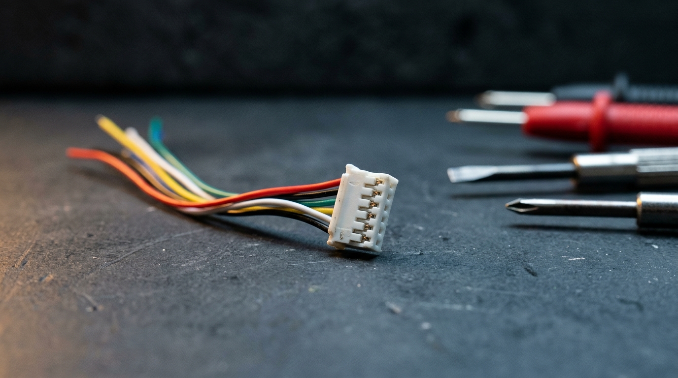
Verify the pin order before you trust the color
A harness that arrives without printed labels is a small puzzle, and the wrong guess is expensive — applying a rail to the video input is how cameras die. An FPV camera pinout copied from a forum is worth exactly as much as the person who posted it, so the two stages below settle the question on your own bench, without applying power to anything you are unsure about. If you have to work out how to wire an FPV camera whose lead you did not build yourself, this is the part that decides whether the camera survives the process.
Stage one, with everything unplugged: find ground first. Set a multimeter to continuity. Probe from a pin you believe is ground to a known ground on the same board — the camera's metal shell, a battery negative pad, or the ground pad beside it. The pin that beeps is almost certainly ground. Do the same check on the power side: a camera supply pin usually shows continuity to nothing else, while a ground pin shows continuity to shields and to other grounds. Ground goes first because the two remaining conductors are only a solvable pair once it is known.
Stage two, still with nothing powered: split the two conductors that are left. Ground is settled, so exactly two conductors remain — one supply, one video — and the check that separates them needs no supply at all. Stay on continuity, plug the harness into the camera with everything unpowered, and probe from each remaining conductor at the loose end to the camera's own board: the conductor that lands on the camera's supply input, the pad that feeds its regulator, is the supply, and the one that lands on its video output is video. The camera is connected but nothing is powered, so a wrong reading costs you a second probe rather than a camera.
If the camera's board is potted, or the pads are too small to reach, no measurement settles the question and a powered trial is not a substitute for one. If you run one anyway, be clear about what protects you: a current limit catches a short and nothing else. Back-feeding a camera's video output draws far less than any sensible limit, so the limit will not trip on the wrong guess that matters. A steady, plausible-looking voltage on the meter is not evidence either, because a wide-input camera will accept more than one pin. A 100–470 Ω resistor in series with the feed is the protection that changes the outcome: it caps what a wrong pin can draw at tens of milliamps instead of whatever the supply is willing to deliver — the difference between a survivable mistake and scrap.
What this buys you is a pin identity that comes from the hardware rather than from a color. It also explains why a harness that worked on one camera can fail on the next: same connector shell, different pin order, and the color convention that seemed reliable was never a convention at all.
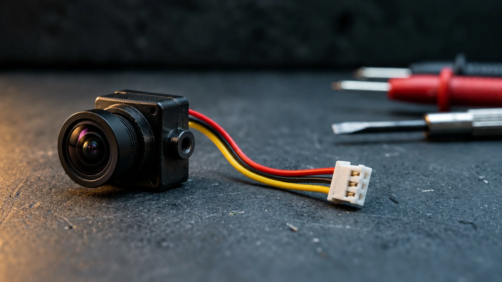
The illustrative bench scene above shows an FPV camera and its three-wire harness. A matching connector does not guarantee a matching pinout: identify signal, power and ground from the exact hardware documentation, and confirm the camera's rated voltage before connecting power. Wire colors alone are not proof of pin function.
Either way, the published specification for your exact module is the only pin and rail claim worth trusting. The VTX specifications by model pages list the harness and camera supply model by model, which makes them the document to open before you start probing a lead you did not build.
Single-point grounding and the return path
Composite video is a single-ended signal: roughly one volt peak-to-peak delivered into a 75 Ω load, measured against ground (composite video). Everything the camera sends is defined relative to that reference. If the reference moves, the picture moves with it.
A ground loop is what happens when there is more than one return path between the same two points. The loop behaves like a small antenna and a small resistor at once: current flowing in one branch induces a voltage in the other, and the video signal — which is measured against ground — picks it up. That is the mechanism behind hum bars, moving bands and noise that changes with throttle rather than sitting still (ground loop).
The rule that follows is simple to state and easy to break: the camera's ground should return to the unit that supplies its power, through the same connector the power arrived on. Two common topologies and what that means:
- Camera powered from the VTX output. The camera's ground returns through the same harness to the transmitter. Video also lands on the transmitter. One supply, one return, one reference — this is the arrangement with the fewest return paths, and it is the reason the direct topology is worth considering even when you want an OSD.
- Camera powered from a flight controller pad. The camera's ground returns to the controller. If video then runs straight to the VTX, you have created a second path: camera ground to controller, controller ground to VTX, VTX ground back to the camera through the video lead's shield or the frame. That is a loop. Either route the video through the controller as well, or move the camera's power to the transmitter so both ends agree.
None of that contradicts the opening section. A shared ground is not the fault; a shared ground that carries more than the camera's own return is. The reference moves when something else is flowing in that conductor — a second return path, or a high-current return sharing the same wire — because the voltage the video is measured against is then set by a current the camera does not control. Putting the camera's power and its return on one connector is what leaves that conductor carrying only what it was meant to carry.
The mistake to avoid is treating "everything is grounded, so it is grounded correctly". Continuity between two grounds tells you they are connected; it does not tell you the current is returning the way you intended. The frame, the PDB and the video shield can all be carrying return current you never planned for.
Route the lead away from high-current paths
Once the electrical decisions are made, the physical routing decides whether they survive contact with a flying machine.
Keep the camera lead out of the neighborhood of the ESC phase wires and the battery main leads. Those carry switching currents with fast edges, and a signal wire running parallel to them for any distance picks up what they radiate. Where the two must cross, cross at a right angle rather than running alongside; crossing is a point, running parallel is an antenna.
Keep the video conductor and its ground together for the length of the run. Twisting the pair or keeping them in the same sheath holds the loop area small, which is the same argument as the grounding section, applied to geometry instead of topology. A video wire routed alone around one side of the frame and its ground around the other is a loop with a large area and a predictable result.
Fix the harness at both ends so that vibration loads the solder joint as little as possible, and leave a service loop at the camera end so that changing a lens or a mount does not pull on the pads. Thin wire is easier to route and worse at carrying current: if the camera misbehaves only when the motors spin up, a long, thin supply run with real voltage drop is one of the things to suspect before blaming the camera.
Symptom → cause: what to measure first
Symptoms are the fastest way into this, provided you read them in the right order. The table below is ordered from "check before you change anything" outward.
One assumption behind the table: these rows assume the camera passes through the flight controller. On a direct camera → transmitter build the controller never sees the video, so overlay presence cannot be used to split the rows; treat every row as "no controller overlay" and work down the list in order.
Symptom | Most likely layer | First measurement | What the result tells you |
|---|---|---|---|
Black screen, no overlay either | Video path or camera power | Camera supply voltage at the camera end, under load | A rail that collapses under load points at the source, not the camera |
Black screen, overlay visible | Camera output, or the camera → flight controller conductor (camera supply at the camera end) | Camera supply voltage at the camera end, and continuity from the camera's video conductor to the controller's camera-input pad | The overlay reaches the transmitter on the same conductor as the picture, so an overlay without a picture proves that conductor and the transmitter are working — nothing is arriving from the camera |
Fine white or black lines across the picture | Ground reference or routing | Whether the camera ground returns to the supplying unit | A second return path shows up as line noise that survives camera swaps |
Noise that follows throttle | Routing, ground loop, or supply sag | Route of the camera lead relative to the ESC phase wires; rail voltage at full throttle | If the rail holds and the routing is clear, look for the loop |
Voltage reading jumping in the overlay | Sensing scale, or the ground reference and the supply | Compare the reading against a multimeter at the same pad, then watch both while the load changes | A steady offset that does not move with load points at the sensor's scale or calibration; a reading that moves with load points at grounding or supply sag |
Camera reboots when arming | Supply sag or current limit | Rail voltage during the throttle burst | A dip below the camera's minimum is a supply problem, not a video problem |
Judge the fault on the goggles, and keep a DVR recording of it while you work: a fault that is present in the recording came in from upstream of the display, so it is in the link rather than in what you are looking at.
If the harness checks out and the picture is still wrong, stop testing the wire. The next step is tracing video faults by symptom with the rest of the chain in view, because a symptom that survives a known-good harness is no longer a wiring problem.
Before the first power-up, run the short version of the same list: confirm which conductor is which with the meter rather than the color, confirm the camera's input range against its own label, confirm the ground returns to whatever supplies the power, fit the antenna before applying power, and leave the props off until the picture is stable. Every one of those is cheaper than the component it protects.
If you are specifying transmitters rather than wiring one, the harness is part of what you are buying: a printed pin function on the diagram, a labeled connector, and a camera rail whose value is stated per model save the integrator an afternoon of probing. That is the standard the transmitter range is documented to, and the pin functions above come from those manuals rather than from a wiring convention.