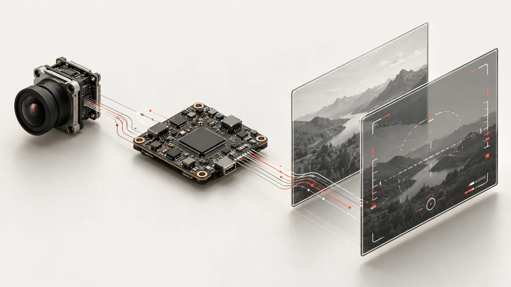
FPV OSD is an on-screen display that places information over a first-person-view camera image. The camera supplies the scene; a flight controller, camera or separate device supplies and renders the information. Battery voltage, timers and signal indicators can therefore share one screen while coming from different parts of the system.
That distinction matters when something looks wrong. A clear picture with a missing voltage value is a different problem from a picture that disappears altogether. To understand either, follow the data and the video as separate paths until they meet.
FPV OSD has a data source and a drawing stage
An overlay has three jobs behind it: obtaining a value, deciding what to display, and drawing the result. Those jobs may live on the same board, but they are still different jobs.
A flight controller can collect readings from onboard circuitry and connected devices, combine them with software state, and prepare an OSD layout. An analog OSD circuit then inserts characters into the camera signal. The video transmitter, or VTX, carries that combined picture to a video receiver, or VRX, which feeds a display.
The Analog Devices MAX7456 description provides a useful hardware example: it is a character-based OSD generator with a serial interface and support for PAL and NTSC video. It is a drawing component, not a GPS receiver or battery sensor. Other designs use different chips or rendering methods, so the exact board documentation still matters.
For any number on your screen, ask two questions: which device knows this value, and which device draws it? A label alone cannot answer either.
- SourcesSensors · receiver · timer
- Flight controllerSelects values and layout
- OSD rendererDraws the information
- CameraCreates the scene
- Overlay stageAdds the characters
- VTX → VRX → DisplayCarries and shows the picture
Where common on-screen values come from
A useful source map separates measured values, calculated values and software state. The following are common arrangements, rather than a universal specification for every flight controller.
Screen element | Typical source | What to establish |
|---|---|---|
Battery voltage | A voltage-sensing input or reported battery data | Which battery or supply is being measured |
Current or consumed capacity | Current sensing or supported telemetry; capacity may be accumulated from current over time | Whether the source exists and is configured correctly |
GPS ground speed or satellite count | A connected GPS receiver and flight-controller processing | Whether the receiver has valid data |
Flight timer | Firmware timing logic | Which event starts or stops the timer |
RSSI or link quality | Data from the relevant receiver/link | Whether the indicator describes the control link or the video link |
The ArduPilot OSD panel reference explicitly distinguishes items such as primary battery voltage, GPS satellites and RC received signal strength. That last label is easy to overlook: a healthy control-link reading does not establish that the separate video link is healthy.
A displayed number also does not prove that its source is calibrated or that it is the quantity you intended to monitor. Treat the source definition as part of the display configuration.
Analog video and DisplayPort place the overlay differently
In a conventional flight-controller-based analog arrangement, the camera's video passes through the overlay hardware before it reaches the VTX. The characters become part of the video signal. A compatible downstream receiver and display can show them without independently reconstructing the original sensor values.
Digital OSD can use a different route. With a supported MSP DisplayPort arrangement, the flight controller sends display instructions to the digital video system, which renders the overlay through its supported implementation. The layout and available elements depend on the firmware and receiving system.
The official Betaflight OSD Tab documentation covers both analog MAX7456-based devices and digital systems that accept MSP DisplayPort. It also documents PAL, NTSC and HD layout modes. An OSD tab is therefore not evidence that a board includes analog video-overlay hardware.
This is an architectural distinction, not a pinout. Before connecting hardware, use the documentation for the exact board revision and firmware. A connector that carries control commands is not automatically the same path that carries the camera image.
Camera OSD and flight-controller OSD can coexist
Some cameras generate their own menus or overlays. For example, the official RunCam Racer 5 manual describes camera OSD items including pilot identification, a timer and pitch information, alongside its built-in gyro. Those features belong to that camera; they are not proof of what another camera supports.
This explains why changing a flight-controller layout may leave some characters untouched. A camera-generated item may already be present in the picture before the flight controller adds its own overlay. A goggle menu can add yet another visible layer at the receiving end.
Identify the owner of the item before changing a setting. If two timers disagree, first check whether they come from different devices or start events. If two voltage readings differ, establish their measurement points before assuming that one display is defective.
Read the symptom before changing a setting
The source map gives you a way to narrow a question without trying unrelated fixes.
- Camera image present, flight-controller overlay absent: inspect the intended rendering path and whether that path is supported and enabled. The working picture does not prove the overlay stage is in use.
- Overlay present, one value missing or implausible: inspect that value's source, availability, units and configuration. Drawing other characters successfully does not validate every sensor input.
- Readable values cut off at the edge: inspect the layout against the actual video mode and display area.
- Wrong symbols or corrupted characters: inspect the font and renderer configuration for the installed firmware. Betaflight's documentation specifically identifies font upload as a possible remedy for incorrect glyphs.
These observations identify the layer to investigate; they do not establish a single cause. A firmware-specific troubleshooting procedure should come from the documentation for the hardware in front of you.
Start with a source map for your setup
Before your next FPV OSD setup change, record the few elements you actually need. For each, write down its data source, renderer, unit and expected behavior. Keep the camera, flight controller and display model names beside that record.
You will then be able to ask a precise support question: “The flight-controller timer is visible, but this battery reading has no valid source,” rather than “the OSD is broken.” That distinction makes both documentation searches and hardware discussions more useful.
To follow what happens after the picture is assembled, read about analog FPV latency from camera to display.