Interference is the one fault in FPV where the picture is a poor witness. Uniform snow, random sparkles, sliding bands and a picture that snaps between clean and ruined can all come from the same three doors: noise generated on your own aircraft, something that happens between the two antennas, or a receiver that is being overwhelmed rather than deprived. The sources of FPV interference are not a long list to memorize. They are a short list to eliminate, one door at a time, cheapest test first.
What follows is that elimination order. It assumes the picture is already bad and that you would rather spend ten minutes on the bench than a week swapping parts.
Start with what changes, not what it looks like
Two aircraft can show identical interference and have nothing in common. One has a motor lead running against the camera harness; the other is parked beside a pilot on a neighboring channel. The picture cannot separate them, because both produce broadband noise that the receiver cannot distinguish from a weak carrier.
What separates them is not appearance but dependence: the one variable that makes the fault better or worse. Before touching hardware, ask what makes it change, and watch for four answers.
What makes it worse | Where it usually enters | What that rules out | Start at |
|---|---|---|---|
Throttle, not distance | Supply path and ground reference on the aircraft | Air path, receiving antenna, receiver tuning | Pass 4, then back to 3 |
Position or heading, not throttle | Obstruction, reflection, polarization | Supply path, receiver tuning | Pass 6, then 2 |
Another pilot powering up | Co-channel congestion or receiver overload | Your own wiring | Pass 5, then 1 |
Nothing you did — same aircraft, different site | Ambient spectrum at that site: Wi-Fi, site infrastructure, other services | A fault that is independent of site noise. It does not rule out hardware whose margin has already shrunk; that one comes back when you return, which is what pass 6 is for | Pass 1, then 6 |
Two rows can be true at once, and often are. The table is not a diagnosis; it is a way to delete three-quarters of the suspect list before you open a toolbox. That is the whole premise of a source-by-source approach to FPV interference: rank the doors before you rank the parts. Write the answer down, because the second half of this article is a sequence of tests, and a sequence is worthless without a baseline to compare against. The last column is the handoff into that sequence — it names the pass to open with, not the pass that matters most.
One boundary worth fixing now. If the whole frame dissolves into even, grain-like snow that thickens steadily with distance, the mechanism is the link's noise threshold rather than a discrete interference source, and it is worked through separately in FPV video noise: tracing the snow on screen. What this article covers is everything that arrives on top of that: structured noise, bands, sparkles that come and go with an external cause. The full map of symptoms and components sits in interference and video fault troubleshooting.
On-board sources: the FPV interference your own aircraft generates
The aircraft is the one suspect a pilot never investigates, because it is the thing that worked yesterday. It is also the noisiest object in the link: a switching regulator, three or four motor phases, a camera, and a video transmitter, all sharing one battery and one ground. Every one of them is a candidate source of electromagnetic interference, or EMI, and the video conductor is the wire that collects them.
Two coupling paths matter, and they are worth naming because each has a different fix. Conducted noise travels on the supply and ground conductors. Radiated noise leaves a wire and arrives at another wire, which is why harness routing beats component swaps. The other two frequent suspects on an aircraft are not coupling paths at all, and treating them as one sends you looking for a shield that does not exist. A thermal fold-back is a power step that quietly drops: it looks like interference, it is not, and the response is mounting and airflow. A loose connector is plumbing rather than physics — a shell threaded on but not making contact — and it reads as a fixed loss rather than as noise.
Power rails and ground loops
An ESC does not draw current smoothly; it chops it. That chopped current, plus the inductance of the battery lead, produces ripple on the supply, and any regulator or reference that shares that rail inherits it. Whether the ripple reaches your video depends on something less obvious: where each device thinks ground is.
A ground loop forms when two devices are connected by more than one path to ground, and the difference in potential between those paths appears as a signal. Camera fed from a regulator, VTX fed from the battery pads, both grounded at different points on a carbon frame — the video conductor now carries the voltage difference between those two grounds, and it carries it straight into the transmitter's modulator.
There are two fingerprints here, and they are worth keeping apart, because they point at different parts of the supply. Ripple-type noise is clean before arming, grows in proportion to throttle, and recovers when you drop throttle. Step-type noise appears the instant the aircraft arms and does not follow throttle position at all — something is being switched on, or a ground reference is stepping as the current path changes. Both are unchanged by antenna swaps, and both are confirmed the same way: if the picture is clean on the bench with the ESCs unpowered, the noise was arriving through the supply.
The minimum test costs one small battery. Power the camera and transmitter from it, isolated from the flight pack, and leave everything else alone. If the picture cleans up, the fault is in the supply or the ground reference and no antenna will ever fix it. If the picture stays dirty, the noise is being radiated into the harness rather than conducted, and the next section applies.
Where suppression lands is a matter of the airframe, not a universal recipe: a single ground reference for camera and transmitter, a regulator with headroom rather than one running at its limit, bulk capacitance close to the load and an LC filter in front of the transmitter when the noise is conducted, and — when the noise is common-mode rather than on the supply — a ferrite clamp around the camera lead, which raises the impedance that common-mode current has to push through without touching the normal-mode signal carried inside the coax. That is why a clip-on choke sometimes changes a symptom that no capacitor fixed, and why fitting one at random and calling it a filter is not the same as knowing which current you are trying to stop. The relationship between power, heat and supply is treated at length in transmitter power, heat and power supply.
The camera harness is an antenna you installed
Composite video is a single-ended signal on a 75-ohm line, carried on coax for a reason: the shield is the return conductor for the signal, and it only works as one if it is continuous from the camera connector to the transmitter connector and bonded to the local ground at each end. The current that leaves the camera on the center conductor comes back on the inside surface of that shield. That is the normal-mode path, and anything that interrupts it — a loose pair of wires instead of coax, a shield that stops at a cut, a connector whose braid is not clamped — costs you the return path as well as the impedance the 75-ohm figure describes. The coaxial cable article is a useful refresher on why the geometry, not the conductor, does the work.
Bonding both ends is therefore right on the video line, and it is also where the trouble starts, because those two bonds give the shield a second path to ground for whatever else is flowing. Current riding the outside surface of the shield is common-mode current, and it does not cancel: the potential difference between the camera end and the transmitter end adds in series with the video signal, which is how a continuous, correctly bonded shield still puts a slow band or a drift into a picture. The fix for that current is not to lift one end — lifting an end opens the signal return and leaves the video dangling. It is to raise the impedance the common-mode current has to push through, with a ferrite clamp around the lead close to the transmitter, and in stubborn cases to give camera and transmitter a single shared ground reference instead of two.
The rule that a shield is bonded at one end only belongs to a different cable, and this is where it is usually borrowed from the wrong one. Where a camera lead is a three-wire ribbon — signal, power and a dedicated ground — and a braid or drain wire has been added over it, the return path is the ground wire, not the braid. Bond that braid at both ends and it becomes a parallel return: it carries a share of the ground current, that current meets the field around the motor leads, and the resulting potential rides along the harness where the video signal can pick it up. Bonded at the camera end only, the braid does the job it was added for — screening the ribbon — without becoming a second return path.
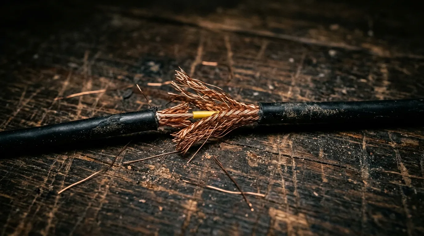
The fingerprint here is fine, high-frequency speckle and thin diagonal streaks that get worse as the harness runs closer to a motor lead, unaffected by throttle in some builds and throttle-dependent in others. The test is a reroute, not a purchase: lift the camera lead away from the power leads, cross at a right angle where they must cross, and fly the same line. How the camera, the flight controller and the transmitter share a signal and a ground is covered in camera to VTX wiring.
Heat, and the power step that quietly drops
A transmitter's rated output is a condition, not a constant. Modules hold their setting while the die stays inside its thermal window and give it up when it does not — some fold back in steps, some shut down and restart, and the ones that fold back produce a picture that degrades after a few minutes and recovers after a rest. That pattern gets read as interference because it looks like the link losing margin.
Standing still on the bench is the worst case you will ever present to the module: no airflow, often maximum power, and sometimes no antenna connected at all. An unterminated output reflects nearly everything back into the amplifier, which is the single fastest way to make a transmitter hot and unhappy. If your "interference" only appears during bench work, stop diagnosing and put the antenna on.
The test is environmental rather than electrical. Note how long the picture stays clean from a cold start, then repeat with airflow over the module. A picture that stays clean with air and degrades without it is a thermal story, not a radio story, and the correct response is mounting and airflow — thermal path to the frame, air moving over the body, antenna always fitted — never a higher power setting, which makes it worse. The threshold temperature is a property of the module; use the figure in that module's own manual rather than borrowing one from a different model.
Connectors that are on but not connected
A threaded connector can be fully engaged and still be an open circuit at radio frequencies. The center pin can be recessed, bent, or pushed back into the dielectric after one too many tight landings. The braid can be loose inside the connector body. And SMA and RP-SMA are visually similar enough to be mated by force, in which case the two center contacts press against each other instead of mating and nothing radiates.
The consequence is described by impedance matching: whatever is not accepted by the antenna is reflected back toward the amplifier, and reflected power is margin you paid for and did not get. Return loss and VSWR are two ways of quoting the same mismatch. You do not need an instrument to act on it — a substitution test finds it in under a minute, and it is the only test in this article that catches an antenna fault without flying.
The path: what happens between the two antennas
Everything above is on the aircraft. Everything below happens in the space between two antennas, where the only variable you control is geometry.
Multipath, and the obstruction you cannot see
Reflections arrive after the direct signal, at a different phase. Depending on that phase, they add or subtract, so the received level moves up and down as the geometry changes — which is why multipath interference shows up as an amplitude ripple rather than a steady loss, and why multipath propagation is best understood as a geometry problem. On an FM video link this reads as a picture that pulses, tears, or drifts through slow brightness bands in a rhythm tied to your position rather than your throttle. The displaced second image people call ghosting is the same mechanism seen on an AM picture: an FM receiver has a capture effect, so the weaker path is suppressed rather than drawn beside the strong one, and what reaches the screen is sync tearing and banding instead of a double image.
The part that surprises people is that "line of sight" is not the test. Clearance is quantified by the Fresnel zone, the elliptical volume around the direct path that must be substantially unobstructed for the path to behave like free space. A treeline, a ridge, a building edge or the roof of a car can graze that volume while leaving the aircraft perfectly visible, and the loss arrives without any visible cause. This is why the same aircraft flies clean over one field and poorly over the next, and why the fail pattern follows heading rather than distance.
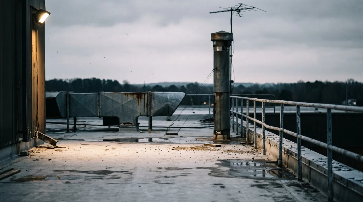
Every metal surface in a scene like this one is a second path to the receiver, and the ductwork is as good a reflector as the railing: the reflections do not need to be in front of the aircraft, only somewhere the receiving antenna can see.
The fingerprint: it changes when you change position or heading, recovers when you turn back, and ignores throttle entirely. The response is height and geometry — fly the line higher, move the ground station, or change what the receiving antenna is pointed at. Pointing is a trade, because a narrow beam concentrates energy in one direction by taking it from everywhere else, which is the subject of 5.8 GHz antenna gain and beamwidth.
Polarization mismatch
Two antennas transfer power efficiently only when their polarizations agree. Circular polarization comes in two hands, and a right-hand antenna on the aircraft against a left-hand antenna on the ground is a fault, not a preference; a linear antenna working against a circular one gives away a fixed share of the link before geometry enters the argument. The antenna article covers the mechanism without the marketing.
This is what people mean by FPV antenna polarization problems, and the reason it is worth a section is that it drifts. An antenna that can rotate on its mount is an antenna whose polarization is chosen by the last landing. A whip that has been bent back by a crash still radiates, just not in the plane you assume. Both produce a consistent loss in every direction, unaffected by throttle, which is exactly the signature that sends people looking for a broken transmitter.
The test is substitution on the same band, at both ends, one at a time. The other half is mechanical: if the mount allows rotation, it will rotate, so mark the position or use a mount that does not. Antenna selection and mounting are covered in FPV antenna selection and installation.
Co-channel congestion and intermodulation
A shared band means shared consequences. Co-channel interference is the simple case: two transmitters close enough in frequency that the receiver cannot separate them, which on an FM link produces the flutter of a receiver switching between two similar carriers rather than a gradual fade.
The non-obvious case is intermodulation. When two strong signals meet a nonlinear stage — and a receiver front end near its limit is nonlinear — they mix and produce products at predictable offsets, with the third-order term landing at twice one frequency minus the other. Two pilots on well-separated channels can therefore ruin a third pilot's channel that neither of them is anywhere near. Intermodulation is the mechanism; the practical consequence is that "we are all on different channels" is not the same claim as "our channel plan is clean".
The fingerprint: it starts when a specific other aircraft arms, and stops when it lands. Nothing on your machine changed, and nothing on your machine will fix it. What does help is a channel plan with enough separation, a pit mode or low power setting while you are on the ground, and the discipline of powering up one aircraft at a time.
The transmitter side of the same coin is worth one sentence, because it is the part owners cannot fix at the field: no transmitter is perfectly clean, and spurious emission plus harmonic products land outside the assigned channel. A module with a damaged output stage or a badly matched antenna can put energy where its channel label says it should not be, which is how one aircraft upsets a receiver tuned somewhere else entirely. That is a reason to treat a transmitter that runs hot into a bad connector as a suspect for the whole field, not just for its own picture.
Channel tables, band behavior and the arithmetic of separation are the subject of FPV frequency bands and link engineering.
Ground end: when the receiver is the victim
The last door is the one you are holding. Two failure modes live here, and neither is a broken receiver — both are the receiver being asked to do its job in conditions it was not specified for, which is where a surprising share of stubborn FPV interference turns out to live.
Front-end overload and blocking
A receiver front end has a dynamic range. Present it with a very strong signal — a transmitter on the next bench, a site transmitter, a pilot who has just armed at full power — and its first stage stops behaving linearly. Sensitivity then degrades across the band it is tuned to, not only on the offender's frequency, so every channel looks worse at once and the effect disappears when you leave the site. That is blocking, and it is why "my video got bad when he plugged in" is not always a channel conflict.
The fingerprint: everything degrades together, at short range as well as long, and improves when the offending transmitter stops or when you move the ground station away from it. No antenna on your aircraft will change it. If the goggles offer a band scan, or you have a spectrum analyzer within reach, blocking is easy to recognize on the display: a raised noise floor across a wide slice of the band, rather than one narrow carrier sitting on your channel.
Goggle antennas, diversity, and the band table
Diversity reception helps when the two branches receive different signals, and how different those signals are is a question about wavelength rather than about centimeters in the abstract. Two antennas collect essentially the same field when they sit closer together than a fraction of a wavelength. At 5.8 GHz a wavelength is roughly 52 mm, so branches a few millimeters apart are the same antenna twice, while a couple of centimeters already samples a different part of the field and a different set of reflections. Two identical whips of the same type and the same orientation will still collect near-identical signals on a clean direct path at almost any spacing that fits on a set of goggles, which is why orientation is usually the stronger lever: cross one branch to horizontal, or fit a directional antenna on the second connector, and the switching finally has something to choose between.
The test takes seconds and needs no tools. Cover one antenna with your hand and watch; then cover the other. If covering either one changes nothing, one of those paths is not contributing — a bad connector, a broken coax inside a bend, or a diversity stage that is not switching. If both coverings change the picture, both branches are alive and the problem is downstream of the antennas, so look at the switching and the feed before you look at the spacing.
The band table is the other quiet failure. Channel numbers are conventions, not frequencies: the same number means different frequencies on different systems, and a table that does not match the transmitter's actual table produces a picture that is watchable at close range and unusable beyond it. Autoscan is not a fix; it locks onto the strongest signal in the band, which at a busy site is frequently somebody else. Setting band, channel and frequency explicitly — the way Betaflight's VTX documentation describes the table the flight controller holds — removes a whole class of "interference" that was never interference.
Where to intervene first: six passes, cheapest first
Six tests, ordered so that each one deletes a category rather than a single part. None requires an instrument you do not already own, and the first three require no flight at all. The numbers are a cost order, not a diagnosis: the pass you start with is the one your answer in the first table pointed at, and the passes that follow are there to confirm it.
Pass | Action | If the picture changes | If it does not |
|---|---|---|---|
1 | Transmitter off, receiver on, same channel | The site is noisy: go to pass 6 before anything else | Baseline is clean, continue |
2 | Known-good antenna at the ground end, then at the aircraft | Antenna, connector or joint | Rule out both antennas |
3 | Camera harness unplugged at the transmitter | Camera side or harness, not the link | Link or supply, continue |
4 | Camera and transmitter on an isolated battery | Supply path or ground reference | Radiated noise, continue |
4b | Props off or aircraft restrained: one motor powered at a time | A speckle pattern with one motor only: that phase's lead or its routing | Radiated noise is not motor-borne, continue |
5 | Different band or channel, same location | Frequency-specific: co-channel or filtering | Not frequency-specific |
6 | Ground station or flight line moved | Site: obstruction, reflection, ambient spectrum | Hardware, after all |

Pass 1 is the one people skip, and it is the most informative: with your own transmitter off, the screen shows you the site's noise floor and nothing else. A receiver displaying structure with nothing of yours transmitting is telling you the answer to half the checklist already.
Pass 3 needs a caveat. Unplugging the camera proves the camera side is involved only if the noise disappears; if the picture goes black and the noise goes with it, you have learned nothing, and the test has to be run as a substitution instead — a known-good camera or a known-good short harness, one variable at a time.
Pass 4 divides the noise into conducted and radiated and stops there; it does not tell you which part of the aircraft is doing the radiating. That is what pass 4b is for, and it is the only test in the sequence that points at a single wire. With the props off — or the aircraft restrained on the bench — power one motor at a time and watch a static picture. A speckle pattern that appears with one motor and not the others fingers that phase's lead, its joint, or the way that lead runs past the camera harness, which is exactly the case where a reroute is the fix and no part gets replaced. If all four motors produce the same pattern, the source is common to the whole power train and the answer is a supply or grounding change rather than a routing one.
Pass 6 is also where ambient spectrum belongs. Site infrastructure raises the noise floor across a wide slice of the band rather than sitting on one channel — Wi-Fi access points in the 5 GHz bands, radar-adjacent services, broadcast sites — and a band scan, or a move several channels away, separates it from anything the aircraft is doing.
Record the passes as you go, because a week later the only thing you will remember is the conclusion you liked.
Pass | What changed | What the picture did | Verdict |
|---|---|---|---|
1 | |||
2 | |||
3 | |||
4 | |||
4b | |||
5 | |||
6 |
If the sheet ends with the picture unchanged after all six, the fault is probably not interference at all: it is margin, and margin is measured rather than guessed — the same fixed-point baseline method, with one variable per flight, that the companion article on video noise sets out.
That leaves two ways forward from the sheet, and neither requires you to draw a conclusion you cannot support. If a pass ends in a decision rather than an answer — the fault follows the site, or the ground end is where the limit sits and you are choosing what to put there — our analog FPV video receivers are listed by frequency range, channel count and input voltage, so you can hold those figures against your transmitter's channel table yourself before deciding anything.
If the passes contradict each other, or the sheet is full and the picture is still not explained, send it to us through the contact page: which transmitter and which receiver, which pass you started at, what you changed, what the picture did, and a short clip if you have one. A finished record sheet gives us something to work from that a description of a symptom does not, and it usually saves a round of questions.
What this checklist cannot tell you
Three limits are worth stating plainly, because a checklist that oversells itself gets abandoned after the first wrong answer.
It cannot tell you whether the link has enough margin. Margin is a comparison between two flights, not a property visible in one frame, and no amount of staring at a still image substitutes for a repeatable baseline.
It cannot separate analog interference from digital link behavior. A digital system does not produce interference patterns in the analog sense; it holds a clean picture and then stops holding it, in blocks, in a freeze, or in a bitrate that collapses. If the aircraft is on a digital link, most of this checklist applies to the antennas and almost none of it to the picture. The difference between the two is covered in analog and digital FPV.
And it cannot replace the documentation for the specific hardware in your hands. Channel tables, input voltage ranges and connector types differ by model, and a table borrowed from a different module is worse than no table at all — where a manual is missing, treat the pinout and the channel map as unconfirmed rather than assuming the common arrangement.
Which leaves the useful version of the whole article in one sentence: find the variable that changes the fault, and you have already found the door it came through. Everything after that is confirmation. Start with the pass your first answer pointed at.