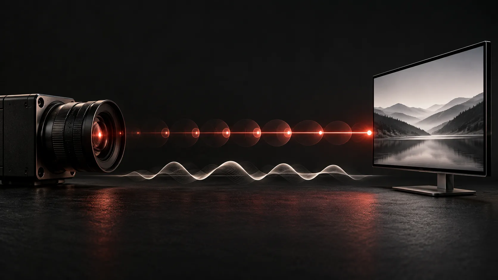
Analog FPV latency is the delay between a change in the scene seen by a camera and its appearance on the viewer's display. That end-to-end path includes image capture, camera processing, video transmission, reception and display behavior. A latency figure describes a particular measurement boundary and setup, not every system carrying analog video.
A camera's minimum-delay specification and a complete camera-to-goggle measurement can both be correct while showing different numbers. Before comparing them, establish where each clock starts and stops.
Define the endpoints of analog FPV latency
“Latency” can describe several different measurements:
Measurement | Start and end | What it leaves out |
|---|---|---|
Camera latency | A scene change to the camera's video output | Downstream transmission and display |
Video transport latency | A defined transmitter input to a defined receiver output | Camera capture and final screen behavior |
Glass-to-glass latency | A scene change at the camera to a visible change on the viewing display | The separate command path from radio controls to aircraft response |
Even glass-to-glass tests need a precise endpoint. Detecting the first changed pixel is different from waiting for a chosen area of the display to reach a specified brightness. Results should state what was detected and where.
Video delay also differs from control-link latency. If a test begins with a stick movement and ends with visible motion, it can include control transmission, processing and mechanical response as well as the video return path. It cannot isolate the video system by itself.
Follow the picture through the complete chain
Start with light reaching the sensor. The camera must acquire the image, read it out and perform its image processing before delivering video. Exposure settings and operating mode are therefore part of the setup you need to document. An analog output does not tell you everything about the processing inside the camera.
Next comes any overlay or other device in the video path, followed by the VTX and video receiver. A conventional analog video link carries a continuously varying video signal rather than using the same compressed-frame delivery model as some digital systems. That architectural difference does not make the complete path instantaneous.
Finally, the receiver's output must become visible on a screen. Include the actual goggles or monitor, the selected input, and any adapter between the receiver and display. If you view the feed through a USB capture device and a computer application, that capture and presentation path belongs in the measurement too.
For practical reasoning, divide the chain into camera, intermediate video hardware, transport and display. Use that map to identify what changed between tests. Do not assign a guessed millisecond allowance to each box and present the sum as a measured result.
- CameraExposure · readout · processing
- Video linkOverlay · VTX · VRX
- DisplayInput processing · visible pixels
Analog input can still involve digital display processing
An analog signal at the input does not mean the display uses an entirely analog internal path. Video may be decoded, digitized, scaled or converted from interlaced fields before it reaches the panel.
A concrete FPV example appears in the official HDZero Goggle Operation documentation. Its analog-input section describes a decoder with an adaptive comb filter, a deinterlacer and an upscaler. This establishes that processing exists after analog reception; it does not establish a universal delay for those stages or for other goggles.
At the component level, Analog Devices' ADV7186 documentation describes analog-video digitization, deinterlacing and scaling in a display processor. It is an architecture example, not evidence that a particular FPV headset contains that component.
Consequently, changing the viewing device can change the path even when the camera and RF hardware stay the same. Record the input mode and processing configuration rather than treating “analog goggles” as one interchangeable test condition.
Read minimum, average and worst-case claims differently
A minimum is the lowest reported value under the stated conditions. It does not describe the average, the variation between observations or the complete delay through additional equipment.
For example, the RunCam Robin manual lists camera latency as 6 ms minimum. That is a useful illustration of why the qualifier matters. It is not a promise that any complete link using that camera will deliver a 6 ms glass-to-glass result, and it should not be carried over to another camera model.
Video timing also needs context. PAL and NTSC labels describe signal formats; a field is not the same thing as a complete interlaced frame. A frame or field rate alone does not disclose how a camera or display handles buffering. Avoid turning a rate into a universal end-to-end delay by simple division.
The same comparison rule applies when reading claims about DJI, HDZero or Walksnail: use the stated camera, mode, display and measurement method. A technology label is not a substitute for those details.
Keep a record that makes two results comparable
A useful latency record should let another person understand what was measured without reconstructing the setup from a screenshot. The following is a reporting checklist, not a claim that MASA has carried out a benchmark.
Record | Detail to retain |
|---|---|
Camera | Exact model, firmware where applicable, video standard and image settings |
Video path | Overlay devices, VTX, receiver, adapters and selected operating modes |
Viewing endpoint | Goggle or monitor model, input and relevant processing settings |
Measurement method | Scene-change stimulus, detection criterion, instrument or recording rate |
Observations | Number of samples, minimum, representative value, maximum and test duration |
Conditions | Lighting and any configuration changes between runs |
If you estimate delay by counting frames in a recording, make the arithmetic visible: elapsed time equals the counted intervals divided by the recording frame rate. At a true 240 frames per second, one interval is approximately 4.17 ms. This is an arithmetic example, not a measured FPV result or a guarantee of 4.17 ms accuracy. Recording cadence, exposure, rolling shutter and your detection criterion can affect the interpretation.
A single favorable sample is not a distribution. Repeat observations and retain the range rather than selecting the lowest result. When comparing two configurations, keep the stimulus and detection method consistent and document every changed component. If the endpoints differ, label the results as different measurements.
Ask for the chain behind the number
When someone gives you an analog FPV latency figure, ask for the camera, receiving display, settings and measurement endpoints that produced it. Ask whether the figure is a minimum, an average or a complete observed range.
Those details turn “low latency” into an assessable claim. Until they are available, keep a component specification separate from a complete-system result—and leave an unmeasured value unmeasured.
For a closer look at the overlay stage, see where FPV OSD data comes from.