A band letter is a table, not a frequency
Channel 4 is 5805 MHz on band A, 5790 on band B, 5645 on band E, 5800 on band F and 5769 on band R. Five different frequencies, one label, every one of them sold as "5.8 GHz". Nothing about that is a mistake in the hardware. It is what happens when a band gets named after its approximate position, then gets filled in by five manufacturers who each numbered eight channels from their own starting point.
That naming is the first thing to fix before planning anything. The 5.8 GHz FPV channels in common use run from 5645 MHz at the bottom of band E to 5945 MHz at the top of it — 300 MHz of spectrum, much wider than the 5725–5875 MHz ISM allocation that gives the band its name. Only part of what a modern video transmitter calls 5.8 GHz sits inside that ISM block. The rest sits in spectrum that other services also use, under rules that differ by country.
The distinction matters before any channel is chosen: these tables are what the hardware can transmit, not what you are permitted to transmit. The 5645–5945 MHz span crosses at least three different allocations, and some of the channels below are outside the unlicensed allocation in the US, the EU, or both. Confirm your local allocation before you build a plan on a frequency from this article.
Band letters are conventions, not standards. A, B and E carry Boscam's lettering, F comes from ImmersionRC and Fatshark, R from Raceband; the low bands carry other letters again. Their tables are now baked into module firmware and, since Betaflight 4.1, into the flight controller's own VTX table, where each band is a name, a letter, a factory flag and eight frequencies. When you select "R6" you are selecting a row and a column of a table that lives in the transmitter, and the flight controller is told which row and column you want — not which frequency.
This article is about that table and the space between its columns: why the steps are 20 MHz, which channels overlap when they are not 20 MHz apart, what else is transmitting in the same spectrum, and how many aircraft a single site can actually hold. It is part of the wider FPV frequency bands and link engineering problem, which starts from the physics of the band rather than from a channel list.
The short version, before the arithmetic: eight channels is a count of table entries, not a count of pilots. Four aircraft on one band is a plan that mostly holds. Six needs frequencies drawn from more than one band and spaced unevenly on purpose. Eight at one site is a digital-link figure, or a figure for two separate flying areas, not something a single analog band delivers.
Why the tables sit on 20 MHz steps
An analog FPV video link is a frequency-modulated carrier carrying a composite video signal, and its bandwidth is set by how far the carrier swings and how fast the video signal moves. Carson's rule gives the approximation: bandwidth is twice the sum of peak deviation and the highest modulating frequency. Put a 4 MHz deviation behind a video signal with roughly 6 MHz of baseband and the number lands at about 20 MHz. Measure a real module and the figure comes out larger — a widely used FPV reference puts the 5.8 GHz analog channel at 30 MHz of bandwidth. The gap between the two numbers is the audio subcarrier and the sideband tail that the 98% Carson contour leaves out, which is exactly the part that decides how much a channel leans into its neighbor.
Either figure explains the grid. A 20 MHz step was never a guard band; it was the width of the signal, rounded. Eight channels at 20 MHz spacing fill 140 MHz edge to edge with nothing between them, which is exactly what the first generation of single-band video transmitters did.
The useful quantity is not the step but the space left over. Subtract what a signal occupies from the distance to its neighbor:
Signal occupancy | 19 MHz step (B) | 20 MHz step (A, E, F) | 37 MHz step (R) | 40 MHz step (H, L) |
|---|---|---|---|---|
20 MHz | −1 MHz | 0 MHz | +17 MHz | +20 MHz |
30 MHz | −11 MHz | −10 MHz | +7 MHz | +10 MHz |
Negative numbers are overlap: at a 20 MHz step and 30 MHz of occupancy, each channel reaches 5 MHz into the channel below and 5 MHz into the channel above. Two neighbors on adjacent channels are therefore sharing 10 MHz of spectrum, always, by construction.
That is not automatically a fault. Selectivity is the receiver's job, and an FM receiver has a second mechanism that makes the sharing survivable: the capture effect. When two signals arrive inside the passband, the receiver demodulates the stronger one and suppresses the weaker. You do not get a mix of two pictures; you get one picture, chosen by which aircraft is closer.
What you get instead, when the two are close to equal, is the receiver switching between them — picture tearing, sync loss, a frame that alternates between two aircraft. Adjacent-channel interference is the sum of two things that both belong to the hardware: how much energy the transmitter puts into the neighboring channel, and how much of it the receiver's filter lets through. Neither is zero on any module you can buy. This is why "we are 20 MHz apart" is a statement about a frequency plan, not a statement about isolation.
The tables: A, B, E, F, R and the low bands
These are the eight-channel tables as they appear in current module firmware and in the Betaflight documentation. Frequencies in MHz.
Band | Ch 1 | Ch 2 | Ch 3 | Ch 4 | Ch 5 | Ch 6 | Ch 7 | Ch 8 | Step | Span |
|---|---|---|---|---|---|---|---|---|---|---|
A (Boscam A) | 5865 | 5845 | 5825 | 5805 | 5785 | 5765 | 5745 | 5725 | 20 MHz | 140 MHz |
B (Boscam B) | 5733 | 5752 | 5771 | 5790 | 5809 | 5828 | 5847 | 5866 | 19 MHz | 133 MHz |
E (Boscam E) | 5705 | 5685 | 5665 | 5645 | 5885 | 5905 | 5925 | 5945 | 20 MHz + 180 MHz gap | 300 MHz |
F (Fatshark / IRC) | 5740 | 5760 | 5780 | 5800 | 5820 | 5840 | 5860 | 5880 | 20 MHz | 140 MHz |
R (Raceband) | 5658 | 5695 | 5732 | 5769 | 5806 | 5843 | 5880 | 5917 | 37 MHz | 259 MHz |
Read the columns, not the rows, and four things fall out.
A is the only band that sits entirely inside the ISM block on a clean 20 MHz grid. All eight channels sit between 5725 and 5865, at exact 20 MHz steps, with the lowest one on the ISM lower edge. B is also fully inside the block, but its 19 MHz step means it is not on the grid. That makes A easy to remember and easy to collide with, for a reason covered below.
B is the odd one out at 19 MHz. Seven steps of 19 MHz span 133 MHz, so B drifts against every 20 MHz grid it meets. It is the band that most often produces a "close enough" picture — a receiver set to a channel a couple of megahertz away still shows an image at short range and falls apart at distance.
E is two bands wearing one letter. Channels 1–4 run 5645–5705, channels 5–8 run 5885–5945, and there are 180 MHz of nothing between channel 4 and channel 5. Treat E as two groups of four, never as one row of eight.
R trades granularity for span. Eight channels over 259 MHz at 37 MHz steps. It covers almost the whole analog range and it is the only common band where every pair of neighbors has real space between them — which is exactly why it is the default at events, and why the plan still fails when people assume that means eight pilots.
The less common bands are worth knowing because a receiver that supports them will list them, and because a transmitter set to one of them by accident is a fault that looks like a broken antenna:
Band | Ch 1 | Ch 2 | Ch 3 | Ch 4 | Ch 5 | Ch 6 | Ch 7 | Ch 8 | Step |
|---|---|---|---|---|---|---|---|---|---|
D (Diatone) | 5362 | 5399 | 5436 | 5473 | 5510 | 5547 | 5584 | 5621 | 37 MHz |
O | 5474 | 5492 | 5510 | 5528 | 5546 | 5564 | 5582 | 5600 | 18 MHz |
L | 5333 | 5373 | 5413 | 5453 | 5493 | 5533 | 5573 | 5613 | 40 MHz |
H | 5653 | 5693 | 5733 | 5773 | 5813 | 5853 | 5893 | 5933 | 40 MHz |
Two traps live in these tables. The first is that the same frequency appears in more than one band: F8 and R7 are both 5880 MHz, and A1 at 5865 is one megahertz from B8 at 5866. A pilot who says "I'm on channel 8" and a pilot who says "I'm on R7" may be describing the same carrier, or a carrier one megahertz away, and both will see a picture. The second is that the low bands sit far below 5.8 GHz — L starts at 5333 MHz and D at 5362 — so an antenna cut for 5.8 GHz is a poor match there, and the resulting weak link looks like a range problem rather than a tuning problem.
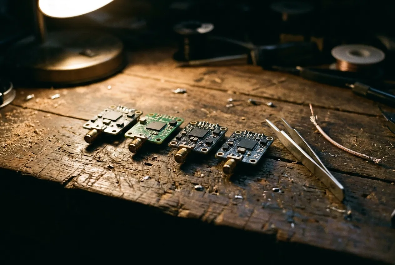
Every one of these boards holds the same table in firmware, and each manufacturer numbers it slightly differently. Reading the table, not the label, is the whole discipline.
Which channels overlap, and which only look like they do
Overlap between your channel and the pilot beside you is the overlap everybody plans for. It is rarely the one that ruins a day, because your neighbor is on the ground most of the time and his transmitter is in pit mode or off. The overlap that hurts is with something that transmits continuously, at a fixed frequency, all afternoon — and in most venues that is Wi-Fi.
The 5 GHz Wi-Fi plan and the FPV band share the same spectrum, and the channel centers interlock in ways that are not obvious from either table alone. In the US, U-NII-3 covers 5725–5850 MHz and U-NII-4 covers 5850–5925 MHz; since 2021 the lower 45 MHz of U-NII-4 has been available indoors for unlicensed use, with 5895–5925 reserved for vehicle-to-vehicle systems. The 20 MHz Wi-Fi channels in that range sit at 5745, 5765, 5785, 5805, 5825, 5845, 5865 and 5885 MHz — Wi-Fi channels 149 through 177, at 20 MHz steps.
Now put the FPV tables next to that grid:
- Band A is the grid. Seven of A's eight frequencies — 5745 through 5865 — are exactly the centers of Wi-Fi channels 149 to 173. A1 at 5865 is Wi-Fi 173. A4 at 5805 is Wi-Fi 161. There is no offset to exploit: an access point on channel 161 is transmitting on your channel, not near it.
- Band F is 5 MHz below the grid. F1 at 5740 sits in the lower quarter of Wi-Fi channel 149's 5735–5755 passband. Every F channel is offset by the same 5 MHz, so F is never clear of a Wi-Fi channel, only off-center inside one.
- Band R drifts across the grid, and the middle of the band lands on it. R1 at 5658 is below U-NII-3, but not outside Wi-Fi: it sits 2 MHz from Wi-Fi channel 132 at 5660, and R2 at 5695 sits 5 MHz from channel 140 at 5700. Both are U-NII-2C channels where an access point has to use radar avoidance, so whether they are carrying anything is site-specific, not fixed. R3 at 5732 falls in the 5 MHz gap between Wi-Fi 144 (which ends at 5730) and 149 (which starts at 5735). But R4 at 5769 is 4 MHz from 5765, R5 at 5806 is 1 MHz from 5805, R6 at 5843 is 2 MHz from 5845. Three of the middle four Raceband channels sit essentially on top of a Wi-Fi channel center. R8 at 5917 is above the unlicensed part of U-NII-4 and 8 MHz below the 6 GHz block, inside the 5895–5925 MHz segment the US reserves for vehicle-to-vehicle systems: quiet where that segment is unused — often the quietest of the eight at an indoor event — and still reachable by a high-power 6 GHz access point in the same room.
- Band E is mostly outside the Wi-Fi block, but not outside Wi-Fi. Channels 1–4 at 5645–5705 sit below U-NII-3, in the part of the band where access points must avoid radar; that does not make them clear channels. E1 at 5705 is 5 MHz above Wi-Fi 140 (5700), E2 at 5685 the same distance above 136 (5680), E3 at 5665 above 132 (5660) and E4 at 5645 above 128 (5640) — the same off-center placement inside a Wi-Fi channel that band F carries, mirrored to the other side of the block, on channels whose use depends on the venue's radar environment. Channels 5–8 at 5885–5945 are above it. E is the band least exposed to a venue's U-NII-3 Wi-Fi, and the one most exposed to antenna mismatch, because its extremes are the furthest from where a 5.8 GHz antenna is tuned.
Band | Below 5725 MHz | Inside 5725–5850 (U-NII-3) | Above 5850 MHz |
|---|---|---|---|
A | 0 | 7 (5725–5845) | 1 (5865) |
B | 0 | 7 (5733–5847) | 1 (5866) |
E | 4 (5645–5705) | 0 | 4 (5885–5945) |
F | 0 | 7 (5740–5860) | 1 (5880) |
R | 2 (5658, 5695) | 4 (5732–5843) | 2 (5880, 5917) |
That table is the answer to a question that gets asked every race weekend: which band should we use indoors? Whichever one puts the fewest pilots inside the Wi-Fi block the venue is actually using — which requires knowing the venue's access points, not just the band letter.
The second overlap is the one with no transmitter behind it. When two carriers meet a nonlinear stage, they mix and produce products at predictable offsets, the strongest of which is the third-order term at twice one frequency minus the other (intermodulation). Equal spacing makes this arithmetic cruel, because the product of two channels lands on a third channel of the same band:
- 2 × 5695 − 5658 = 5732, which is R3
- 2 × 5732 − 5658 = 5806, which is R5
- 2 × 5769 − 5658 = 5880, which is R7
- 2 × 5806 − 5695 = 5917, which is R8
Every one of Raceband's eight channels can be produced by two others in the same table; the four above are the ones worth naming. Put R1, R2 and R3 on the flight line and R3 is receiving a product from the other two, whether or not either of them is close to it in frequency. The same arithmetic applies to every band with a uniform step: even spacing guarantees that some combination of three channels is a self-interfering triple. This is the reason the published multi-pilot channel lists look arbitrary — they are chosen so that no third-order product lands within tens of megahertz of a used channel, which almost always means uneven spacing across more than one band.
Congestion: what else is on the band
A race site is not a quiet field with eight transmitters on it. It is a field with eight transmitters, a timing system, a video production crew, a PA, several hundred phones, and whatever the venue installed before anyone arrived.
The continuous occupants matter more than the intermittent ones, and they fall into four groups.
Wi-Fi access points. In the 5 GHz band they transmit continuously, at fixed 20, 40 or 80 MHz widths, and an 80 MHz channel is four 20 MHz channels bonded together: the block centered on 5775 MHz spans 5735–5815, which covers F1 through F4 along with R4 and R5. When the venue's AP is on that block, no amount of FPV channel planning makes those channels quiet — the honest responses are to move the plan to the top of the band, to ask the venue to move the AP, or to accept a plan with fewer pilots.
Radar and radar-adjacent services. Below 5725 MHz, 5 GHz Wi-Fi has to detect and vacate radar; FPV does not. A low-band plan on E1–E4 or on the D and L bands can therefore be the only thing in the room that is transmitting while a weather or marine radar sweeps through. That is a site-specific risk, not a reason to avoid the low bands, but it is a reason to scan before committing.
The 6 GHz edge. Wi-Fi's 6 GHz band starts at 5925 MHz, 8 MHz above R8. Indoors, that is close enough for a high-power 6 GHz AP to matter at the top of the FPV range, and it is one more reason the top four channels are not automatically the safe ones.
Site plant. LED walls, wireless video senders, wireless DMX, camera links, point-to-point bridges and PA systems all put energy somewhere. Most of it is outside the FPV channels; the noise floor it raises is not frequency-specific, which is why a site can be clean on every channel at 9 a.m. and unusable at 3 p.m.
The only reliable way to find out is to listen. Turn your own transmitter off and scan the band with the receiver at the pilot line, at the time of day the flying happens. That single test — the first pass in the FPV interference checklist — shows you the site's noise floor per channel and separates "my channel is busy" from "this field is busy". A receiver that shows structure with nothing of yours transmitting has already told you which channels to avoid.
How many pilots fit at one site
Start with the arithmetic the tables allow. Take each band's eight frequencies and count how many can be used at once if every pair must be at least a given distance apart:
Band | Step | Pairs ≥ 20 MHz apart | Pairs ≥ 30 MHz apart | What limits it |
|---|---|---|---|---|
A | 20 MHz | 8 | 4 (5725, 5765, 5805, 5845) | Every adjacent pair overlaps at 30 MHz occupancy; sits on the Wi-Fi grid |
B | 19 MHz | 4 | 4 (5733, 5771, 5809, 5847) | 19 MHz step means every other channel only, and it drifts against Wi-Fi |
E | 20 MHz | 8 (two groups of 4) | 4 (5645, 5685, 5885, 5925) | Two clusters 180 MHz apart; antenna match at the extremes |
F | 20 MHz | 8 | 4 (5740, 5780, 5820, 5860) | Sits 5 MHz inside every Wi-Fi channel |
R | 37 MHz | 8 | 8 | Uniform spacing makes third-order products land on channels |
Read the second column as "what the table contains" and the third as "what a single-band plan can carry". For the 20 MHz bands that is eight channels and four usable slots — and that is the arithmetic behind the rule of thumb that a heat is four pilots. Raceband is the exception in the third column, and it has its own failure mode, covered below.
Six is achievable, and it is where planning starts to matter: six needs frequencies from at least two bands, spaced unevenly so that no third-order product lands on a used channel. Published combination lists exist for two to six pilots, and the ones worth copying are irregular by design — Raceband with an F or an A channel dropped in, or a set drawn from three bands. The same reference notes plainly that Raceband's 37 MHz spacing "does not necessarily mean all 8 Raceband channels can be used simultaneously", which is the most useful sentence in any channel guide: it is a spacing figure, not a capacity figure.
Eight is a different problem. It is reachable with digital links, which allocate their own channels and do not put eight carriers into one analog band; it is reachable with two physically separate flying areas; it is not reachable by putting eight analog transmitters on one band and hoping. Even the digital systems rarely deliver eight cleanly — the practical figure quoted for race organization is four to six pilots at a time, with eight as the exception rather than the plan.
Digital and analog on the same site brings its own rules, and they matter because most events are mixed now. A digital system's 25 Mbps mode occupies about 20 MHz; its 50 Mbps mode occupies roughly twice that, so 50 Mbps takes two channels' worth of room out of the plan and should be the first thing to drop when the site is busy. Digital air units briefly transmit on their public channel at power-up, and that channel overlaps analog R6 at 5843 MHz, so analog pilots should treat R6 as unavailable whenever digital pilots are present. Digital goggles also transmit, which is why the advice to keep digital pilots a few meters from analog pilots exists at all. The wider differences between the two link types are covered in analog and digital FPV.
Power is the other half of capacity. A group plan that assumes everyone is at 25 mW behaves very differently from one where three pilots are at 1 W: a strong nearby carrier raises the noise floor for everyone and pushes receivers into the nonlinear region where adjacent-channel and intermodulation effects get worse. For group flying, 200 mW or lower is the usual working figure, and 25 mW indoors. Pit mode exists for the time between flights — most modules can be held at a fraction of their output, or off entirely, while the aircraft is on the bench — and the relationship between power, heat and supply is treated in transmitter power, heat and power supply.
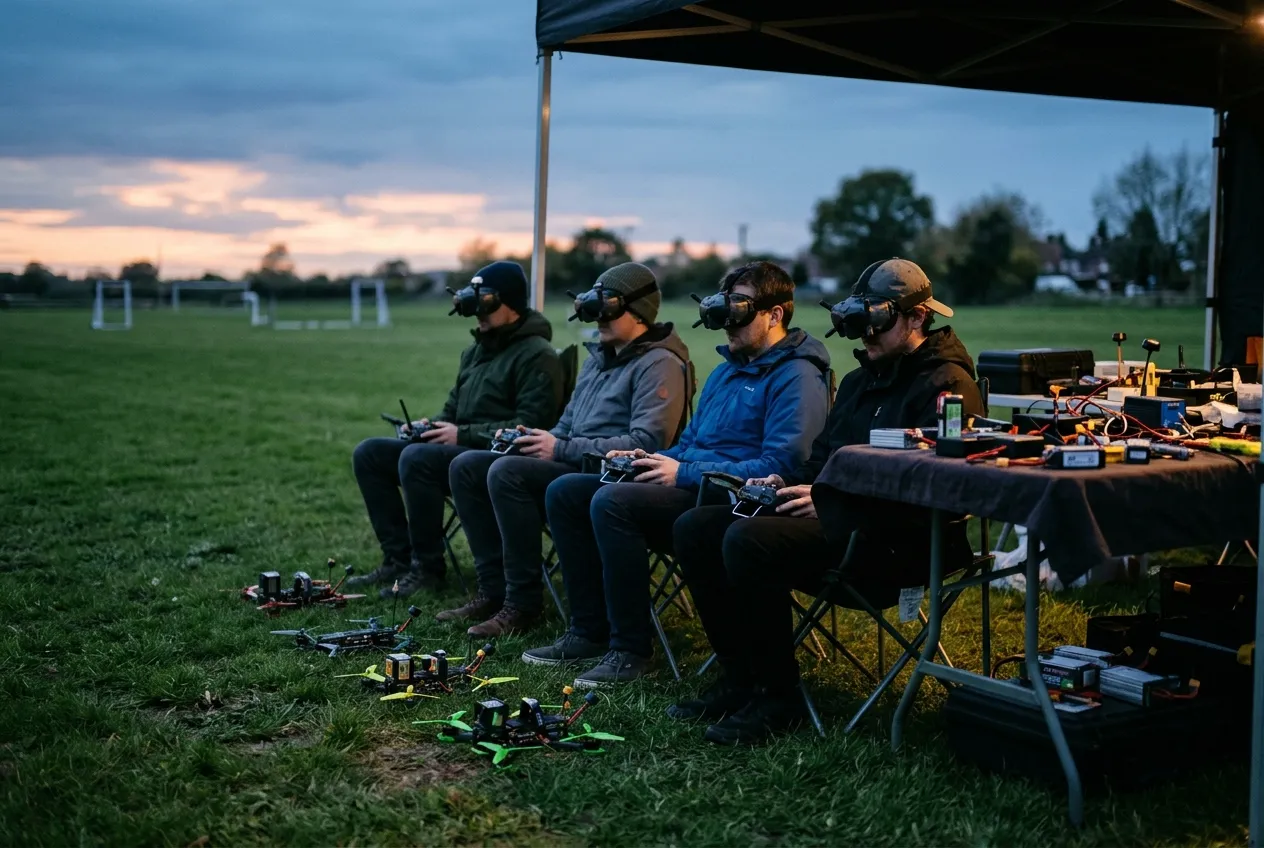
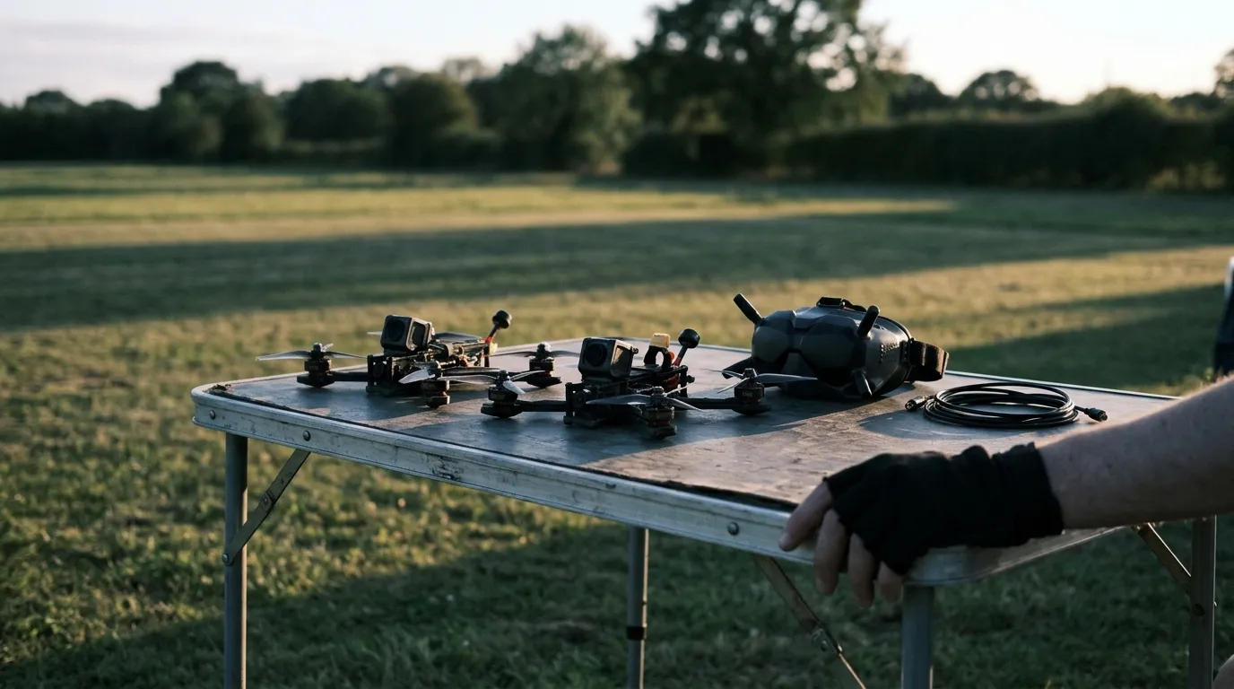
Four pilots, four carriers, one flight line. The spacing that keeps this group flying is decided before anyone arms, not adjusted while they are in the air.
Planning a race day or a multi-operator site
The same procedure works for a club race, a festival with a public flight line, and a permanent installation where FPV has to coexist with the site's own radios. It is nine steps, and the first five happen before anyone arrives.
1. Inventory what the pilots actually have. Band support is a property of the module, not of the hobby. A transmitter with 40 channels may support A, B, E, F and R, or only F and R; a receiver may cover the low bands or stop at 5.8 GHz. Collect the supported bands before designing anything, and treat a model whose manual is missing as unconfirmed rather than assuming the common table — including in our own range, where four receiver models still have no published manual.
2. Choose frequencies, not letters. Write the plan as a list of frequencies in MHz, then map each one to a band and channel per pilot. A frequency survives a module with a different table; a letter does not.
3. Confirm the local allocation. Check each candidate frequency against the rules where the event is actually being held. The bands, the permitted uses and the power limits differ by country, and some channels in these tables sit outside the unlicensed allocation in the US, the EU, or both. A frequency that is not permitted at this site is not a candidate, however well it scores on spacing — drop it and re-run the spacing rules below.
4. Apply three spacing rules. Every pair at least 30 MHz apart. No two channels from the same 20 MHz block. And for every selected frequency, check that twice one minus the other does not land on a third selected frequency — the arithmetic from the previous section, done on paper before the event.
5. Publish the sheet. One row per pilot: name, frequency, band and channel, and the transmitter power to use. Post it where pilots arm, and hand the same sheet to the person running the flight line.
6. Scan the site before the first heat. Receiver at the pilot line, own transmitter off, one pass across the band. If a planned channel is sitting on a continuous carrier, move that pilot before the first battery rather than after the first collision.
7. Hold the pit at low power, and arm one at a time. The most common cause of a ruined heat is an aircraft powering up on someone else's channel while they are in the air. Pit mode, low power and a verbal "arming" call cost nothing.
8. Separate the link types. Analog and digital pilots a few meters apart, digital on 25 Mbps rather than 50, and opposite circular polarization on adjacent analog channels where the antennas allow it — a right-hand antenna against a left-hand one on the neighboring channel buys rejection that no frequency plan can.
9. Re-verify when the lineup changes. A new pilot is a new carrier. Hand them the lowest-risk free frequency from the sheet rather than letting them choose, and re-scan if they bring their own gear.
A worked six-pilot plan, built only from the tables above and labeled as a planning exercise rather than a guarantee:
Pilot | Frequency | Band / channel | Why it is here |
|---|---|---|---|
1 | 5645 MHz | E4 | Bottom of band E, 50 MHz below pilot 2; 5 MHz above Wi-Fi 128, so only where the venue's DFS channels are quiet |
2 | 5695 MHz | R2 | 50 MHz above pilot 1; 5 MHz from Wi-Fi 140, the same DFS caveat |
3 | 5725 MHz | A8 | 30 MHz above pilot 2, on the ISM lower edge |
4 | 5771 MHz | B3 | 46 MHz above pilot 3; B's 19 MHz grid offsets it from the 20 MHz channels |
5 | 5828 MHz | B6 | 57 MHz above pilot 4 |
6 | 5860 MHz | F7 | 32 MHz above pilot 5, 5 MHz below the Wi-Fi 173 center |
Every pair is at least 30 MHz apart, none of the pairs produces a third-order product within 10 MHz of another used channel, and no two pilots share a 20 MHz block. Nothing in the sheet sits above 5860 MHz, which keeps it out of the 5895–5925 MHz vehicle-to-vehicle segment and well below the 6 GHz edge. It is deliberately uneven. The tightest pair is 5695 and 5725 at exactly 30 MHz, and 30 MHz is where two carriers of this width stop overlapping — not where they have margin; if you want margin, drop one of that pair and fly five. A tidier-looking plan — six consecutive Raceband channels — fails the third rule on the first triple you check.
For a permanent or multi-operator site the same sheet becomes a band plan. Reserve the top of the band for FPV if the site's access points sit low; keep the 20 MHz Wi-Fi grid out of the plan if the site uses it; write down what each frequency is for, so that the next person to add a transmitter does not have to rediscover the arithmetic. Integrators who do this once tend to keep the sheet taped inside the case, because the alternative is renegotiating the spectrum every time someone new arrives.
What a channel plan cannot fix
A frequency plan decides who is allowed to collide. It cannot decide who wins the collision, and it cannot repair a link that is short of margin before the first transmitter is switched on.
It cannot compensate for receiver selectivity. A front end with a wide filter hears its neighbors no matter what the plan says, and a strong nearby carrier can push it into overload, which degrades every channel at once rather than one — the mechanism behind "my video got bad when he plugged in", treated at length in the interference checklist.
It cannot fix an antenna. Pattern, polarization and tuning decide how much of the planned separation survives the path; a mismatched antenna at either end costs more than a channel move can recover, which is the subject of 5.8 GHz antenna gain and beamwidth.
It cannot raise a link above its noise threshold. If the snow thickens steadily with distance and no channel is better than another, the limit is margin rather than congestion, and the method for measuring it is in FPV video noise.
And it cannot substitute for the documentation of the hardware in your hands. Channel tables differ by model, letter mappings differ by manufacturer, and a table borrowed from a different module is worse than no table. Where a manual is missing — four receiver models in our own range still are — the honest position is that the channel map is unconfirmed, and the plan should be built from a receiver whose table you can read. Setting band and channel explicitly, rather than relying on autoscan, is the discipline that makes the plan hold; how the flight controller stores and displays that selection is covered in FPV OSD explained.
If you are specifying a receiver for a site rather than flying at one, the figures that matter are the supported bands, the channel count and the frequency range — our analog FPV video receivers are listed that way so the table can be checked against a transmitter's before anything is bought. And if the plan keeps failing for reasons the arithmetic does not explain, the contact page is the place to send the site, the sheet and what the picture did.
The rule that survives every table in this article: a channel number is a pointer into a table, and the table is what transmits. Read the frequency, write the frequency down, and the rest of the plan follows.