The FPV antenna is chosen last and blamed first
The frame is bought, the stack is soldered, the camera is wired, and the FPV antenna is the last line on the order. It is also the first thing anyone blames when the picture goes bad — which is odd, because it is the only part of the video chain that is a piece of shaped metal and nothing else.
An antenna does not add power. It takes the power arriving from the transmitter and decides where that power goes. Two aircraft with identical electronics and different antennas will fly different distances, and the reason is not that one antenna is better. It is that one of them is pointed the right way more of the time.
That reframes the whole question. An FPV antenna selection problem is not a shopping problem with a best answer at the end; it is a constraint problem with three inputs, and they arrive in a fixed order:
- What the airframe can carry — mass, mounting space, and how much leverage that mass has in a crash.
- What the mission does to the aircraft's attitude — how much of the flight the antenna is aimed badly, and at what distance that matters.
- What the link requires — band, polarization sense, connector, and how much loss sits between the transmitter and the radiating element.
Get those three in order and the antenna type falls out almost mechanically. Get them out of order — start from a gain number in dBi, or from a model someone recommended — and you will buy a good antenna for somebody else's aircraft.
The airframe sets the first two constraints: mass and lever arm
On a 5-inch freestyle quad, antenna mass is a rounding error. On a sub-250 g build it is a percentage of the whole aircraft, and it is a percentage hanging off the end of a lever. That difference is not cosmetic; it decides which antennas are even eligible before you look at any electrical property.
The lever is the part people underestimate. An antenna is a cantilever: its mass sits some distance from the point where it attaches, and every crash applies a torque at that attach point equal to mass times distance. A heavy antenna on a long rigid stalk is a small crowbar bolted to your video transmitter. Move the same antenna onto a direct connector on a stack board and the crowbar is now acting on a solder joint. This is why the physical arrangement — not the gain figure — is usually what fails first.
Space is the second half of the same constraint. The antenna needs to sit outside the propeller arc, and it needs a clear view of the direction you actually fly. Both are geometry, and both are decided by the frame:
- Prop arc. A whip that can reach the disc will eventually reach it. On small frames the antenna and the props are competing for the same few centimeters, and a clipped antenna does not fail loudly — it fails as a slight loss of range that nobody attributes to the crash three weeks earlier.
- Frame shadowing. Carbon fiber is conductive, and a frame member between the antenna and the ground station behaves like a shield, not a spacer. Mounting the antenna low and central puts structure in the path for exactly the attitudes you fly most.
- The battery. A pack is a conductive lump with mass. If it sits between antenna and receiver in your normal cruise attitude, your own aircraft is editing the radiation pattern. The fix is boring and effective: get the element above or behind the pack, not alongside it.
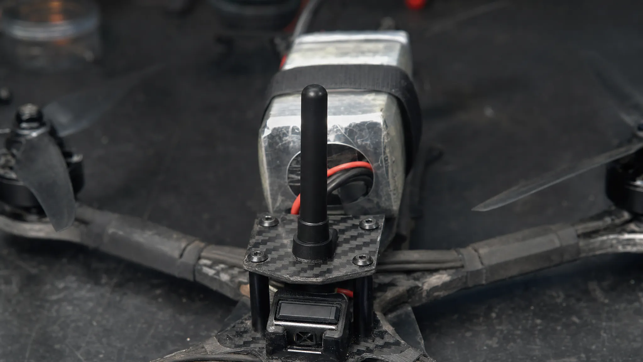
- Mast angle. Most quads cruise nose-down by somewhere in the region of 20–40° depending on tune and speed. A mast fixed at vertical therefore tilts the whole pattern backward in level flight. Mounting the antenna tilted slightly back so that it is close to vertical while cruising costs nothing and is one of the few free wins in this whole subject.
The mission sets the third: how long the antenna is pointed wrong
Distance is the number everyone quotes and the least useful one to design around. The quantity that actually decides whether a link holds is the fraction of the flight during which the antenna is badly oriented toward the receiver — and that is a property of the mission, not of the antenna.
Start with the shape. An omnidirectional antenna's pattern is usually drawn as a doughnut: strong around the sides, weak along the axis. That weak region is real, it is not a manufacturing defect, and it rotates with the aircraft because the aircraft rotates. In a hover, the nulls point up and down and the horizon is well covered. In a 60° dive the pattern has swung with the frame, and the direction that used to be strong may now be pointing at the ground.
The radiation pattern is fixed to the antenna, and the antenna is fixed to the airframe. So the pattern's orientation in the world is a function of how you fly:
- Freestyle and racing spend most of their time within a few hundred meters, changing attitude constantly. Coverage in every direction matters far more than reach in one, because the aircraft may be inverted, knife-edge, or behind a tree at any moment.
- Long range spends most of its time at a shallow angle to the horizon, at distance, with occasional steep climbs and descents. Reach matters, but so does the fact that a high-altitude leg puts the aircraft well above the receiving antenna's horizon line.
- Cinematic and inspection work hovers and creeps. The attitude is stable and the distance is short, so pattern stability matters more than gain.
Two effects sit on top of that and are routinely misread as "the antenna is bad". The first is feed loss: effective radiated power is transmitter output plus antenna gain, quoted in dBi, minus everything lost between them, so a long thin pigtail and a marginal connector can quietly cancel the gain you paid for. The second is obstruction, including ground proximity on low passes — the clearance you need around the direct path grows with distance, and flying low over terrain eats margin that no antenna can restore.
This is also where gain gets misused. Gain raises effective radiated power in one direction and lowers it everywhere else; it does not raise the total. Gain is quoted in dBi, decibels relative to an isotropic radiator, and circularly polarized antennas are sometimes quoted in dBic, which is the same scale measured against a circular reference of the same sense. A 3 dB difference is a factor of two in power on either scale. If the aircraft is inside the beam when it matters, gain helps. If it is outside the beam for a third of the flight, the gain is a loan you repay at the worst moment. The arithmetic of gain and beamwidth is covered in detail in 5.8 GHz antenna gain and beamwidth; the point here is narrower — a gain figure tells you what happens when you are aimed, and nothing about how often you will be.
Directionality belongs to whoever can aim
Once you accept that, the omni-versus-directional question stops being a preference and becomes an assignment of roles.
The aircraft cannot aim. It is the thing being aimed at. It rolls, yaws, and inverts, and it has to be heard from wherever the pilot happens to be standing. Putting a directional antenna on the aircraft means pointing a beam at the ground for a fraction of each maneuver and pointing it at the sky for the rest. This is why a directional antenna on a multirotor is almost always the wrong answer, and why the recommendation shows up in every serious guide.
The ground station can aim. It sits on a tripod or a fence post, it faces a flying area you chose, and it does not move. Directional gain is available there essentially for free — the only cost is that you have to keep pointing it, which is a discipline problem rather than an equipment problem. If your receive side is two identical omnis, you are leaving the cheapest gain in the system on the table.
That is also the honest case for diversity receivers: not that two antennas are magically better, but that an omni and a directional fail in different places. The directional one carries the long leg; the omni covers the moment the aircraft comes back over your head or slips outside the cone. Two antennas of the same type in the same orientation mostly duplicate each other's coverage.
A decision table for six airframe classes
The table below is the constraint set from the previous four sections, applied. Read the last two columns first: they are what you are buying into, and they are the two columns no product listing gives you.
Airframe class | What the frame can carry | Transmit side | Receive side | What you give up | First failure you will see |
|---|---|---|---|---|---|
Sub-250 g whoop, 65–85 mm wheelbase (31–51 mm props) | Very little mass margin; antenna mounts on the AIO board through a tiny connector | Short, light circular omni, guarded or enclosed | Omni only; goggles are usually the limiting factor | Durability and polarization purity | Antenna in the prop wash, or a torn board pad after a hard landing |
2.5–3.5 in cinewhoop, ducted | Tight stack, ducts around the props, little clean airflow for the element | Short omni kept clear of the duct lip | Omni plus a small patch for the working direction | Reach, and pattern stability behind the ducts | Duct edge shadowing the element, or a prop strike on the antenna |
5 in freestyle | Room for a short mast, and enough mass that antenna weight is not the constraint | Circular omni on a short mast, clear of the props | Omni plus a patch, both same sense | Very little; this is the balanced case | Crash damage to the element or a bent connector, not electrical failure |
5 in race | Minimal structure, mass and drag both matter | Low-profile stubby circular omni | Omni only; a narrow beam is a liability at race distance | Gain, deliberately | Antenna clipped on a gate, or a loosened connector from vibration |
7 in long range | Room for a tall mast, a large pack, and a heavier element | Circular omni high on a mast, above the pack | Omni plus a high-gain directional, optionally tracked | Portability, and the omni null matters more at altitude | Polarization mismatch after a swap, or feed loss on an over-long pigtail |
Fixed wing / large multirotor | Space and payload for almost any element | Two circular omnis, clear of the fuselage and the pack | Directional ground station, tracked if the mission is long | Nothing structural; the airframe can carry the right answer | Antenna buried in the fuselage, or shadowed by the battery in a turn |
The two rows people get wrong are the ducted cinewhoop and the long-range build, for opposite reasons. On the cinewhoop the failure is geometric — the ducts and the frame sit in the pattern, and no amount of gain compensates for a plastic lip in the path. On the long-range build the failure is usually arithmetic: a tall mast, a long pigtail, and a directional antenna that is aimed slightly off combine to spend the gain the build was designed to deliver.
The antenna families you will actually be sold
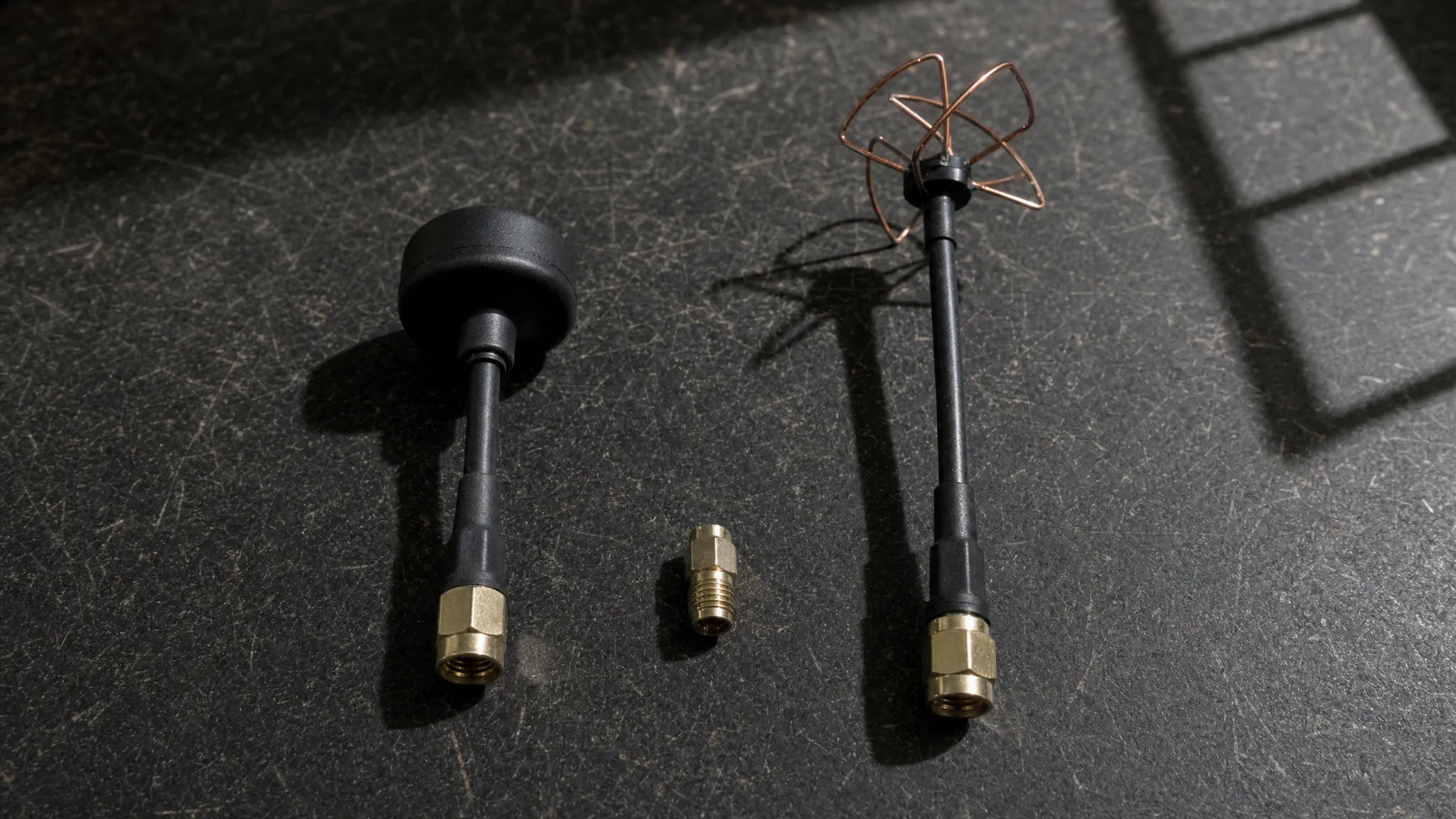
The table describes what the link needs; the shelf labels it by family. There are four FPV antenna types in common use, and each name implies a polarization, a pattern shape and a bandwidth — not a performance grade.
Cloverleaf, also sold as skew-planar. Four curved lobes arranged around the axis and fed so that the lobes produce a circularly polarized omnidirectional pattern. The match stays useful across the 5.8 GHz band and the sense is fixed by the geometry rather than by tuning, which is why it is the usual transmit-side element on an aircraft. Its axial ratio is best near the middle of the band and drifts toward the edges.
Pagoda. A stack of PCB discs doing the same job — circularly polarized, omnidirectional, flat to mount — but with the axial ratio held more evenly across a wider slice of the band. That bandwidth, rather than any gain advantage, is what people pay for, and it is why the type is common on the ground station as well as on the aircraft.
Helical. A helix wound around an axis, radiating a circularly polarized beam along that axis. It is the directional family: the beam is narrow, so whatever gain it offers is only available while it is aimed. That makes it a ground-station antenna on a mast or a tracker, for the reason in the previous section — the aircraft cannot aim.
Dipole. Two linear elements in line, radiating a linearly polarized omnidirectional pattern, usually inside a molded whip or a stubby housing. It is the simplest way to get a signal out of a small frame, and it carries the linear-polarization costs described in the next section: fades that track attitude, no rejection of reflected signals, and a fixed loss when it is paired with a circular antenna at the other end.
To map the two: the "circular omni" entries in the table are cloverleaf or pagoda; a directional entry on the receive side is a helical or a patch; a plain whip or stubby on a small linear link is a dipole. Read the family name for the shape of the pattern and the polarization, not for a gain figure — two antennas in the same family can be built to very different sizes, and the gain follows the size and the pattern, not the label.
Polarization is a property of the link, not of the antenna
Circular polarization is usually introduced as a feature of a particular FPV antenna. It is more useful to think of antenna polarization as a property of the pair. A circularly polarized wave rotates as it travels, and a receiving antenna only extracts it efficiently if it rotates the same way. Right-hand and left-hand are conventions, not quality tiers — but they have to match at both ends.
Three consequences follow, and each one shows up as a real flight problem:
Count the antennas, not the link. If your goggles carry two antennas and only one matches the aircraft's sense, the mismatched one is not a spare — it is a dead branch that the receiver may still switch to. Any swap that changes sense needs to change every antenna in that link at once.
Reflections reverse the sense. A circularly polarized wave that bounces off a surface arrives with its rotation reversed, which is precisely why circular polarization tolerates multipath so much better than linear does: the reflected copy is rejected by the receiving antenna instead of competing with the direct path. That mechanism only works if both ends are circular and matched. Put a linear antenna at one end and you have given up the property you were paying for.
Linear and circular do not mix well. Combining the two costs on the order of 3 dB in the ideal case — half the power — and more in practice, because real antennas are never perfectly circular and the loss then depends on how the two happen to be rotated relative to each other. On an aircraft, that last part is fatal: the relative rotation changes every time the airframe rolls, so the loss becomes a fade that tracks your attitude.
The connector is a mechanical part before it is an electrical one
Every guide says to check the connector. Almost none says why it matters beyond fit, and the reason is that the connector is where the electrical and mechanical problems meet.
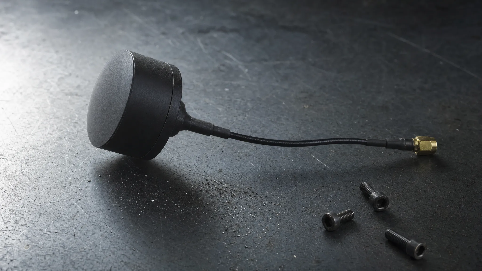
SMA and RP-SMA are not interchangeable. They share a thread and differ in which side carries the pin, so they will happily screw together and then fail to make contact — or damage each other in the attempt. There is no performance argument between them; there is only the question of which one your hardware actually has (SMA connector).
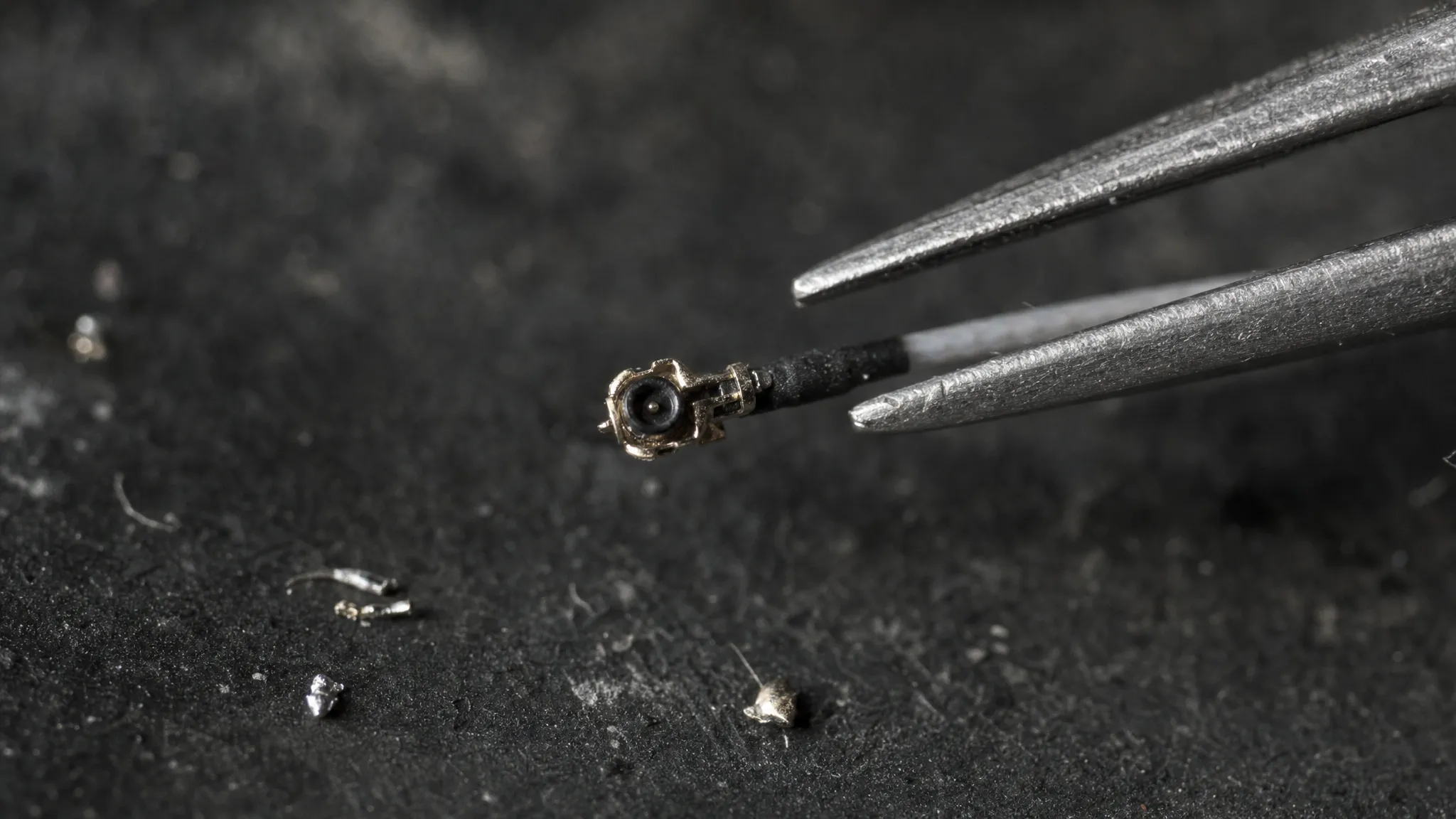
U.FL is a board-level part. It is small, it is rated for a limited number of mating cycles, and it is easy to damage with a sideways pull (U.FL). On a whoop or a 20×20 stack it is often the only option, which means the antenna's mass and leverage are being carried by one of the smallest connectors in the aircraft.
MMCX sits between the two — sturdier than U.FL, smaller than SMA, and rotatable, which takes some of the strain off the cable.
Pigtails are lossy, and more so at 5.8 GHz. Loss in a coaxial cable rises with length and with frequency, so the same short jumper that is acceptable at 2.4 GHz is a measurable cost at 5.8 GHz (coaxial cable). Short, thick, and well-terminated beats long and convenient.
A bad match loads the transmitter. When the antenna and the feed do not match, power reflects back toward the amplifier instead of radiating; that is what the standing wave ratio describes. The practical version: a damaged connector or a wrong antenna does not only cost you range, it puts reflected power into a part that was not designed to absorb it.
This is not theoretical bookkeeping. Within MASA's own 5.8 GHz tables, a 5 W module and an 8 W module in the same 25 g, 36×36 mm format are listed with different connectors — MMCX on one, SMA on the other. If one manufacturer's same-band, same-size, same-weight modules do not share a connector, then "check the exact model" is not a formality; it is the step that decides whether the antenna you bought can be attached at all. The wiring side of the same install is covered in camera to VTX wiring.
What the video is telling you
Most people search for FPV antenna advice after something has already gone wrong. Working backwards from the symptom is faster than reading a catalogue, because different faults fail at different distances and in different directions.
What you see | Most likely cause | Check first |
|---|---|---|
Snow and breakup inside 50 m, on the bench or hovering close | Wrong polarization sense, wrong port, or an antenna not actually connected | Sense at both ends, then connector seating and pigtail continuity |
Clean close in, then a steady decline past a few hundred meters in every direction | Link margin — gain, feed loss, or transmit power — not a fault | Antenna class against the mission, then connector and cable losses |
Clean ahead, drops when you turn and come back | Receive-side directional antenna aimed at the wrong part of the sky, or the omni's null | Aim, mast height, and where the diversity antennas point |
Fades that track attitude — worse inverted, or in a specific bank angle | Null or linear-polarization orientation moving with the airframe | Whether the element is circular, and how it is mounted |
Intermittent breakup that correlates with throttle or vibration | Mechanical: loose connector, strained pigtail, U.FL lifting off the pad | Strain relief, connector seating, cable routing |
Worse only when other pilots are flying | Channel congestion, not the antenna | Channel choice and spacing — see 5.8 GHz channels |
Worse near structures, bridges, or buildings, fine in the open | Multipath and obstruction | Antenna placement and polarization, then expectations |
Two of those rows are worth separating carefully, because they are the ones people misdiagnose for months. A fault that appears close in is almost always a mismatch — wrong sense, wrong connector, damaged cable. A fault that appears at range, in every direction, gradually is almost never a broken part; it is a link that was never big enough for the mission. Replacing an antenna to fix the second case is how people end up with a shelf of antennas and the same problem. The background on what interference actually is, and what it is not, is in where FPV interference comes from and FPV video noise.
One caveat on reading symptoms: analog and digital links fail differently. Analog degrades — noise builds, the picture gets worse, you can often fly through it. Digital tends to hold and then break. A symptom table built on analog behavior will mislead you on a digital link, so judge the trend before the single frame.
The order to buy and test in
If you take one thing from this, take the sequence. It is the same sequence whether you are building one aircraft or specifying a fleet.
- Fix the polarization sense for the whole fleet and write it down. One sense, applied to every antenna in every link, removes an entire category of failure that cannot be diagnosed from the ground.
- Decide the connector family per airframe class before you shop. SMA for the frames that can carry it, MMCX or U.FL plus a short pigtail for the frames that cannot. Do this from the hardware's specification, not from the photograph.
- Choose the receive side first. Gain is cheapest where aiming is possible, and the ground station is the only place aiming is possible. An omni and a directional on a diversity receiver is the default answer for anything beyond close-range flying.
- Then choose the transmit FPV antenna, subject to mass and lever arm. On a large frame this is almost unconstrained. On a whoop it is the whole decision.
- Test one variable at a time. Same channel, same power setting, same flight path, and deliberately include the worst attitude in the flight, not just the most comfortable one. Two antennas compared on a calm hover have told you almost nothing.
- Re-test after any crash that touched the antenna. Bent elements and half-seated connectors do not announce themselves; they show up as a range you slowly stop trusting.
The antenna you want is the one whose failure mode you can predict. A short omni that loses range gradually tells you something; a high-gain element that drops out when you turn tells you nothing until it is too late. That preference — predictable over impressive — is most of what separates a link that works from a link that happens to work.
From here, the two useful next steps are the antenna selection and installation hub, which collects the type-by-type detail, and scenario and link design, which takes the same constraints and turns them into a budget for a specific flight profile. If you are still choosing the transmitter, transmitter power, heat and power supply covers the other half of the same equation.